2NZ-FE ENGINE MECHANICAL ENGINE UNIT REASSEMBLY
PROCEDURE

 15104E
1.INSTALL STUD BOLT
15104E
1.INSTALL STUD BOLT
Using an E5 "TORX" socket wrench, install the 4 stud bolts.
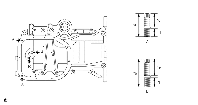
| *a | 22.5 mm (0.886 in.) | *b | 27.5 mm (1.08 in.) |
| *c | 13 mm (0.512 in.) | *d | 8.0 mm (0.315 in.) |
| *e | 16.5 mm (0.650 in.) | *f | 9.0 mm (0.354 in.) |
- Torque:
- 5.0 N*m (51 kgf*cm, 44 in.*lbf)
12101
2.INSTALL OIL PAN SUB-ASSEMBLY
Remove any seal packing from the contact surfaces.
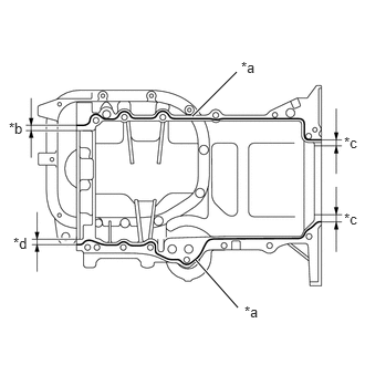
| *a | Seal Packing |
| *b | 9 mm (0.354 in.) |
| *c | 4 mm (0.157 in.) |
| *d | 11 mm (0.433 in.) |
Apply seal packing in continuous lines as shown in the illustration.
- Seal Packing Diameter:
2.0 to 3.0 mm (0.0787 to 0.118 in.)
- Seal Packing:
Toyota Genuine Seal Packing Black, Three Bond 1207B or equivalent
- NOTICE:
- ·
Install the oil pan sub-assembly within 3 minutes of applying seal packing.
·Do not expose the seal packing to engine oil for at least 2 hours after the installation.
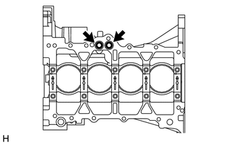
Install 2 new O-rings to the cylinder block sub-assembly.
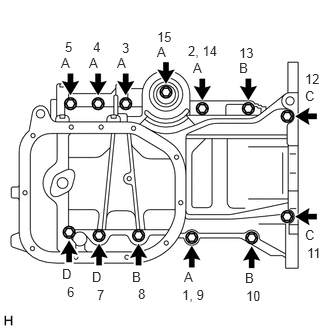
Apply adhesive to the threads of the bolt (D).
- Adhesive:
Toyota Genuine Adhesive 1344, Three Bond 1344 or equivalent
- NOTICE:
-
Do not start the engine for at least 1 hour after installation.
Install the oil pan sub-assembly with the 13 bolts in the order shown in the illustration.
- Torque:
- 24 N*m (245 kgf*cm, 18 ft.*lbf)
- Bolt Length:
Item Length Bolt (A) 49 mm (1.93 in.) Bolt (B) 88 mm (3.46 in.) Bolt (C) 144 mm (5.67 in.) Bolt (D) 88 mm (3.46 in.)
15104
3.INSTALL OIL STRAINER SUB-ASSEMBLY
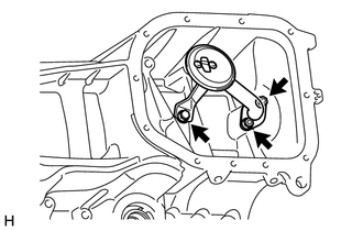
Install a new oil strainer gasket and the oil strainer sub-assembly with the bolt and 2 nuts.
- Torque:
- 16 N*m (163 kgf*cm, 12 ft.*lbf)
12102A
4.INSTALL NO. 2 OIL PAN SUB-ASSEMBLY
Remove any seal packing from the contact surfaces.
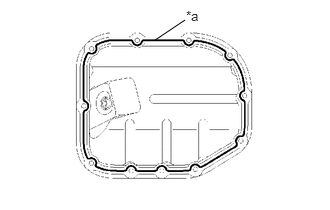
| *a | Seal Packing |
Apply seal packing in a continuous line as shown in the illustration.
- Seal Packing Diameter:
2.5 to 3.5 mm (0.0984 to 0.137 in.)
- Seal Packing:
Toyota Genuine Seal Packing Black, Three Bond 1207B or equivalent
- NOTICE:
- ·
Install the No. 2 oil pan sub-assembly within 3 minutes of applying seal packing.
·Do not expose the seal packing to engine oil within 2 hours of installation.
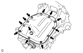
Install the No. 2 oil pan sub-assembly with the 9 bolts and 2 nuts.
- Torque:
- 9.0 N*m (92 kgf*cm, 80 in.*lbf)
Install a new gasket and the oil pan drain plug to the No. 2 oil pan sub-assembly.
- Torque:
- 37.5 N*m (382 kgf*cm, 28 ft.*lbf)
15600A
5.INSTALL OIL FILTER UNION
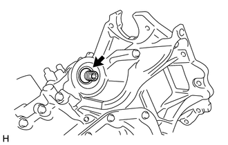
Using a 12 mm hexagon wrench, install the oil filter union to the oil pan sub-assembly.
- Torque:
- 30 N*m (306 kgf*cm, 22 ft.*lbf)
15601
6.INSTALL OIL FILTER SUB-ASSEMBLY
11115
7.INSTALL CYLINDER HEAD GASKET
11101
8.INSTALL CYLINDER HEAD SUB-ASSEMBLY
11401L
9.INSTALL REAR ENGINE OIL SEAL
13050
10.INSTALL CAMSHAFT TIMING GEAR ASSEMBLY
13511
11.INSTALL CAMSHAFT
Apply a light coat of engine oil to the camshaft journals.
Place the camshaft on the cylinder head sub-assembly with the timing mark on the camshaft timing gear assembly facing upward.
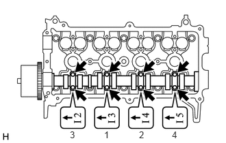
Examine the front marks and numbers on the No. 2 camshaft bearing caps and check that the order is as shown in the illustration. Then uniformly tighten the 8 bolts in the order shown in the illustration.
- Torque:
- 15.4 N*m (157 kgf*cm, 11 ft.*lbf)
- NOTICE:
-
Tighten each bolt uniformly while keeping the camshaft level.
13523
12.INSTALL CAMSHAFT TIMING SPROCKET
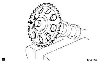
Secure the No. 2 camshaft in a soft jaw vise.
- NOTICE:
-
Do not damage the No. 2 camshaft.
Align the straight pin hole in the camshaft timing sprocket with the straight pin of the camshaft, and install the camshaft timing sprocket to the No. 2 camshaft.
- Torque:
- 64 N*m (653 kgf*cm, 47 ft.*lbf)
13512
13.INSTALL NO. 2 CAMSHAFT
Apply a light coat of engine oil to the No. 2 camshaft journals.
Place the No. 2 camshaft on the cylinder head sub-assembly with the timing mark on the camshaft timing sprocket facing upward.
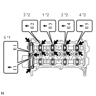
| *1 | No. 1 Camshaft Bearing Cap |
| *2 | No. 2 Camshaft Bearing Cap |
Examine the front marks and numbers on the No. 1 camshaft bearing cap and No. 2 camshaft bearing caps and check that the order is as shown in the illustration. Then uniformly tighten the 11 bolts in the order shown in the illustration.
- Torque:
- No. 1 Camshaft Bearing Cap : 23 N*m (235 kgf*cm, 17 ft.*lbf)
- No. 2 Camshaft Bearing Cap : 15.4 N*m (157 kgf*cm, 11 ft.*lbf)
- NOTICE:
-
Tighten each bolt uniformly while keeping the No. 2 camshaft level.
11101E
14.INSTALL CAMSHAFT POSITION SENSOR
13506
15.INSTALL CHAIN SUB-ASSEMBLY
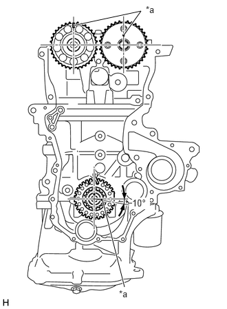
| *a | Timing Mark |
Make sure that all the timing marks are in the positions (TDC) as shown in the illustration.
- HINT:
-
The positions of the timing marks may differ from the predetermined positions due to the force of the valve spring.
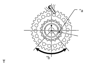
| *a | Timing Mark |
| *b | 40 to 140° ATDC |
Set the timing mark of the crankshaft in a position between 40 and 140° ATDC, as illustrated.
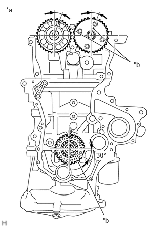
| *a | 20° ATDC |
| *b | Timing Mark |
Set the camshaft timing gear assembly and camshaft timing sprocket in the positions (20° ATDC) shown in the illustration.
Set the crankshaft in the position (20° ATDC) shown in the illustration.
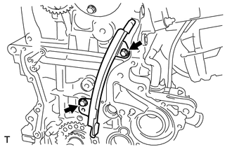
Install the No. 1 chain vibration damper with the 2 bolts.
- Torque:
- 9.0 N*m (92 kgf*cm, 80 in.*lbf)
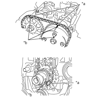
| *a | Mark Plates |
| *b | Timing Mark |
Align the timing marks of the camshaft timing sprocket and camshaft timing gear assembly with the mark plates of the chain sub-assembly and install the chain sub-assembly.
- HINT:
-
Align the timing marks with the mark plates while turning the hexagonal portion of the camshaft using a wrench.
13559
16.INSTALL CHAIN TENSIONER SLIPPER
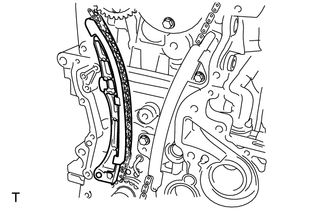
Install the chain tensioner slipper.
13540
17.INSTALL NO. 1 CHAIN TENSIONER ASSEMBLY
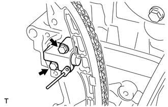
Install the No. 1 chain tensioner assembly with the 2 bolts.
- Torque:
- 9.0 N*m (92 kgf*cm, 80 in.*lbf)
Remove the bar from the No. 1 chain tensioner assembly.
15100C
18.INSTALL OIL PUMP SEAL
15100
19.INSTALL OIL PUMP ASSEMBLY
16100
20.INSTALL ENGINE WATER PUMP ASSEMBLY
12315A
21.INSTALL ENGINE MOUNTING BRACKET RH
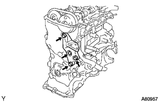
Install the engine mounting bracket RH with the 4 bolts.
- Torque:
- 55 N*m (561 kgf*cm, 41 ft.*lbf)
13407
22.INSTALL CRANKSHAFT DAMPER SUB-ASSEMBLY
Align the pin hole of the crankshaft damper sub-assembly with the pin and install the crankshaft damper sub-assembly.
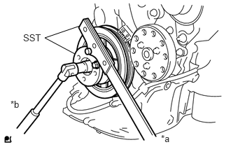
| *a | Hold |
| *b | Turn |
Using SST, hold the crankshaft damper sub-assembly in place and tighten the crankshaft pulley set bolt.
- SST
- 09213-14010 (91651-60865)
09330-00021
- Torque:
- 128 N*m (1305 kgf*cm, 94 ft.*lbf)
- NOTICE:
-
Check the SST installation positions when installing them, to avoid the SST fixing bolts from coming into contact with the oil pump assembly.
16173
23.INSTALL WATER PUMP PULLEY
24.INSPECT VALVE CLEARANCE
25.ADJUST VALVE CLEARANCE
11101J
26.INSTALL CAMSHAFT TIMING OIL CONTROL VALVE ASSEMBLY
23250
27.INSTALL FUEL INJECTOR ASSEMBLY
23291
28.INSTALL INJECTOR VIBRATION INSULATOR
23807V
29.INSTALL NO. 1 DELIVERY PIPE SPACER
23807
30.INSTALL FUEL DELIVERY PIPE SUB-ASSEMBLY
11213
31.INSTALL CYLINDER HEAD COVER GASKET
Install a new cylinder head cover gasket to the cylinder head cover sub-assembly.
11201
32.INSTALL CYLINDER HEAD COVER SUB-ASSEMBLY
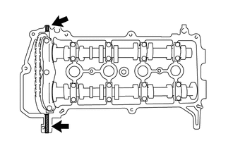

|
Seal Packing |
Apply seal packing as shown in the illustration.
- Seal Packing:
Toyota Genuine Seal Packing Black, Three Bond 1207B or equivalent
- NOTICE:
- ·
Remove any oil from the contact surface.
·Install the cylinder head cover sub-assembly within 3 minutes of applying seal packing.
·Do not start engine for at least 2 hours after installation.
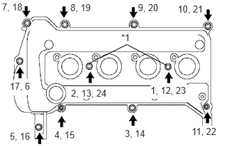
| *1 | Cylinder Head Cover Seal Washer |
Install the cylinder head cover sub-assembly with the 9 bolts, 2 nuts and 2 new cylinder head cover seal washers in several steps in the order shown in the illustration.
- Torque:
- 10 N*m (102 kgf*cm, 7 ft.*lbf)
12204
33.INSTALL PCV VALVE (VENTILATION VALVE SUB-ASSEMBLY)
11452
34.INSTALL OIL LEVEL DIPSTICK GUIDE
Apply engine oil to a new O-ring.
Install the O-ring to the oil level dipstick guide.
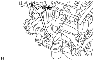
Install the oil level dipstick guide with the bolt.
- Torque:
- 10 N*m (102 kgf*cm, 7 ft.*lbf)
15100Q
35.INSTALL CRANKSHAFT POSITION SENSOR
12108A
36.INSTALL OIL FILLER CAP GASKET
Install a new oil filler cap gasket to the oil filler cap sub-assembly.
12108
37.INSTALL OIL FILLER CAP SUB-ASSEMBLY
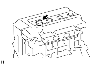
Install the oil filler cap sub-assembly to the cylinder head cover sub-assembly.
16331A
38.INSTALL THERMOSTAT
16321
39.INSTALL WATER INLET
89422
40.INSTALL ENGINE COOLANT TEMPERATURE SENSOR
83530
41.INSTALL ENGINE OIL PRESSURE SWITCH ASSEMBLY
89615
42.INSTALL KNOCK CONTROL SENSOR
19100P
43.INSTALL SPARK PLUG