2NZ-FE LUBRICATION OIL PUMP INSTALLATION
PROCEDURE

 15100C
1.INSTALL OIL PUMP SEAL
15100C
1.INSTALL OIL PUMP SEAL
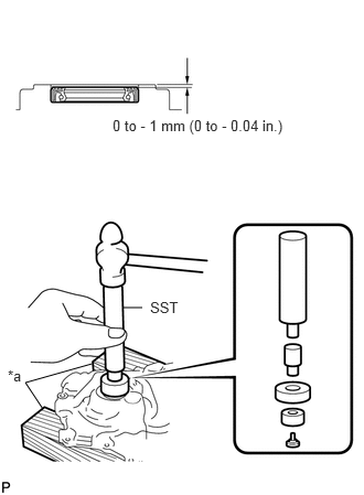
| *a | Wooden Block |
Using SST, tap in a new oil pump seal until its surface is flush with the oil pump assembly edge.
- SST
- 09950-60010 (09951-00250, 09951-00410, 09952-06010)
09950-70010 (09951-07100)
Apply a light coat of MP grease to the lip of the oil pump seal.
- NOTICE:
- ·
Keep the lip free from foreign matter.
·Do not tap in the oil pump seal at an angle.
·Make sure that the oil pump seal edge does not stick out of the oil pump assembly.
15100
2.INSTALL OIL PUMP ASSEMBLY
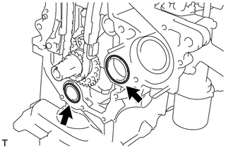
Install 2 new O-rings in the 2 locations as shown in the illustration.
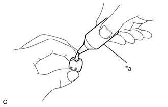
| *a | Adhesive 1324 |
Clean the taper screw plug and the bolt holes of the oil pump assembly and apply adhesive to the threads of the taper screw plug.
- Adhesive:
Toyota Genuine Adhesive 1324, Three Bond 1324 or equivalent
Using an 8 mm hexagon socket wrench, install the taper screw plug.
- Torque:
- 15 N*m (153 kgf*cm, 11 ft.*lbf)
- NOTICE:
-
Do not start the engine for at least 1 hour after installation.
Remove any remaining seal packing material.
Clean the contact surfaces of the oil pump assembly, cylinder head sub-assembly and cylinder block sub-assembly and oil pan sub-assembly, and confirm that no oil, moisture, or other foreign matter is on the surfaces.
Apply seal packing to the engine unit as shown in the illustration.
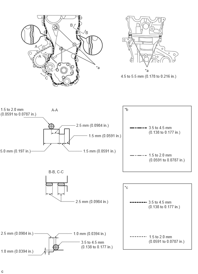
| *a | Seal Packing | *b | Seal Width (Other Parts) |
| *c | Seal Width (Engine Water Pump Assembly Part) | - | - |
- Seal Packing:
- Engine Water Pump Assembly Part:
Toyota Genuine Seal Packing 1282B, Three Bond 1282B or equivalent
- Other Parts:
Toyota Genuine Seal Packing Black, Three Bond 1207B or equivalent
- NOTICE:
- ·
If there is oil on the contact surfaces, wipe them with an oil-free cloth before applying seal packing.
·Install the oil pump assembly within 3 minutes and tighten the bolts within 10 minutes of applying seal packing.
·Do not start the engine for at least 2 hours after installation.
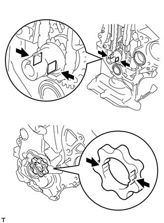
Align the keyway of the oil pump drive rotor with the rectangular portion of the crankshaft, and slide the oil pump assembly into place.
Temporarily install the oil pump assembly and 2 wire harness brackets with the 15 bolts and nut.
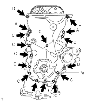
| *a | Wire Harness Bracket |
Tighten the bolts and nut uniformly in several steps.
- Torque:
- Bolt (A) : 32 N*m (326 kgf*cm, 24 ft.*lbf)
- Bolt (B) : 12 N*m (122 kgf*cm, 9 ft.*lbf)
- Bolt (C) : 12 N*m (122 kgf*cm, 9 ft.*lbf)
- Nut (D) : 24 N*m (245 kgf*cm, 18 ft.*lbf)
- Bolt (E) : 24 N*m (245 kgf*cm, 18 ft.*lbf)
- NOTICE:
- ·
Be careful not to disturb the seal packing.
·After applying seal packing to the oil pump assembly, install the engine mounting bracket RH within 10 minutes.
·Do not apply oil to the bolt (A).
- HINT:
-
Each bolt length is as follows.
-
Bolt (A): 30 mm (1.18 in.)
-
Bolt (B): 35 mm (1.37 in.)
-
Bolt (C): 20 mm (0.787 in.)
-
Bolt (E): 14 to 20 mm (0.551 to 0.787 in.), double ended bolt
12315A
3.INSTALL ENGINE MOUNTING BRACKET RH
11101J
4.INSTALL CAMSHAFT TIMING OIL CONTROL VALVE ASSEMBLY
15100Q
5.INSTALL CRANKSHAFT POSITION SENSOR
13407
6.INSTALL CRANKSHAFT DAMPER SUB-ASSEMBLY
12305
7.INSTALL ENGINE MOUNTING INSULATOR SUB-ASSEMBLY RH
Install the engine mounting insulator RH with the 5 bolts and nut.
- Torque:
- 52 N*m (530 kgf*cm, 38 ft.*lbf)
Install the radiator reserve tank assembly with the 3 bolts.
- Torque:
- 7.0 N*m (71 kgf*cm, 62 in.*lbf)
11213
8.INSTALL CYLINDER HEAD COVER GASKET
11201
9.INSTALL CYLINDER HEAD COVER SUB-ASSEMBLY
19500D
10.INSTALL NO. 1 IGNITION COIL
12262
11.CONNECT NO. 2 VENTILATION HOSE
12261
12.CONNECT VENTILATION HOSE
16100
13.INSTALL ENGINE WATER PUMP ASSEMBLY
14.ADD ENGINE OIL
11212
15.INSTALL NO. 2 CYLINDER HEAD COVER
51441C
16.INSTALL ENGINE UNDER COVER RH
17.INSTALL FRONT WHEEL RH
18.INSPECT FOR OIL LEAK