2NZ-FE ENGINE MECHANICAL CAMSHAFT INSTALLATION
PROCEDURE

 13050
1.INSTALL CAMSHAFT TIMING GEAR ASSEMBLY
13050
1.INSTALL CAMSHAFT TIMING GEAR ASSEMBLY
Secure the hexagonal portion of the camshaft in a soft jaw vise.
Check that the straight pin is installed on the camshaft.
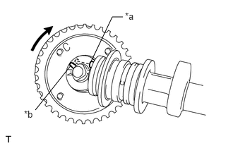
| *a | Straight Pin |
| *b | Key Groove |
Fit the camshaft timing gear assembly and camshaft together with the straight pin and key groove misaligned as shown in the illustration.
- NOTICE:
-
Do not forcibly push in the camshaft timing gear assembly. This may cause the straight pin tip to damage the installation surface of the camshaft timing gear assembly.
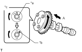
| *a | Straight Pin |
| *b | Key Groove |
| *c | View (A) |
Turn the camshaft timing gear assembly as shown in the illustration while pushing it gently against the camshaft. Push further at the position where the straight pin fits into the key groove.
- NOTICE:
-
Do not turn the camshaft timing gear assembly in the retard direction.
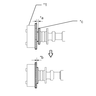
| *1 | Camshaft Timing Gear Assembly |
| *a | Gap |
| *b | No Gap |
| *c | Camshaft Flange |
Check that there is no gap between the camshaft timing gear assembly and camshaft flange.
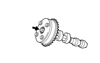
Tighten the bolt with the camshaft timing gear assembly secured in place.
- Torque:
- 64 N*m (653 kgf*cm, 47 ft.*lbf)
- NOTICE:
-
When tightening the bolt, do not allow the camshaft timing gear assembly to rotate.
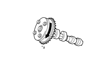
| *a | Lock |
Check that the camshaft timing gear assembly can move in the retard direction (clockwise) and locks in the most retarded position.
13511
2.INSTALL CAMSHAFT
Apply a light coat of engine oil to the camshaft and camshaft journals.
Place tne camshaft onto the cylinder head sub-assembly.
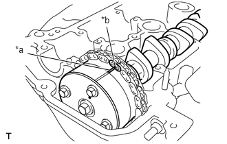
| *a | Timing Mark |
| *b | Paint Mark |
Hold up the chain sub-assembly, align the timing mark and paint mark and install the camshaft to the cylinder head sub-assembly.
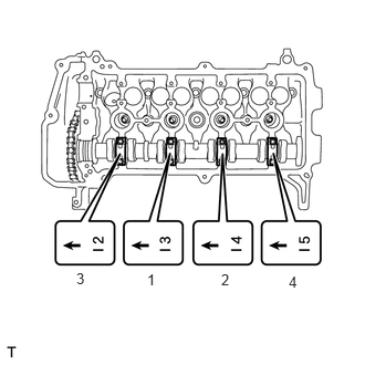
Examine the front marks and numbers on the No. 2 camshaft bearing cap and check that the order is as shown in the illustration. Then uniformly tighten the bolts, in several steps, in the order shown in the illustration.
- Torque:
- 15.4 N*m (157 kgf*cm, 11 ft.*lbf)
- NOTICE:
-
Tighten each bolt uniformly while keeping the camshaft level.
13512
3.INSTALL NO. 2 CAMSHAFT
Place the No. 2 camshaft onto the cylinder head sub-assembly.
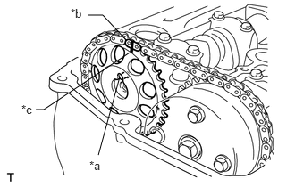
| *a | Straight Pin |
| *b | Paint Mark |
| *c | Timing Mark |
Hold up the chain sub-assembly and align the timing mark on the camshaft timing sprocket with the paint mark of the chain.
Align the straight pin hole in the camshaft timing sprocket with the straight pin of the camshaft, and install the camshaft timing sprocket to the No. 2 camshaft.
Temporarily install the flange bolt.
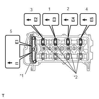
| *1 | No. 1 Camshaft Bearing Cap |
| *2 | No. 2 Camshaft Bearing Cap |
Examine the front marks and numbers on the No. 1 camshaft bearing caps and No. 2 camshaft bearing caps and check that the order is as shown in the illustration. Then uniformly tighten the bolts, in several steps, in the order shown in the illustration.
- Torque:
- No. 1 Camshaft Bearing Cap : 23 N*m (235 kgf*cm, 17 ft.*lbf)
- No. 2 Camshaft Bearing Cap : 15.4 N*m (157 kgf*cm, 11 ft.*lbf)
- NOTICE:
-
Tighten each bolt uniformly while keeping the camshaft level.
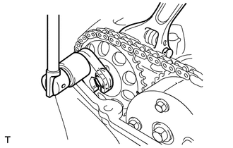
Using a union nut wrench, hold the hexagonal portion of the No. 2 camshaft and tighten the flange bolt.
- Torque:
- without SST : 64 N*m (653 kgf*cm, 47 ft.*lbf)
- with SST : 59 N*m (602 kgf*cm, 44 ft.*lbf)
- HINT:
-
The "with SST" torque valve is effective when using a torque wrench with a fulcrum length of 300 mm (11.8 in.) and a union nut wrench with a fulcrum length of 25 mm (0.984 in.).
-
Click hereGeneral>INTRODUCTION>REPAIR INSTRUCTION>PRECAUTION
Remove the bar from the No. 1 chain tensioner assembly.
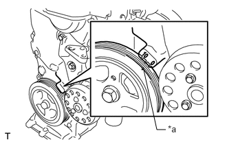
| *a | Timing Notch |
Turn the crankshaft damper sub-assembly until its timing notch (groove) and the timing mark "0" of the oil pump assembly are aligned.
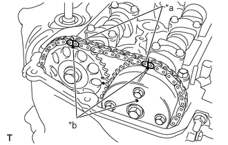
| *a | Paint Mark |
| *b | Timing Mark |
Check that all the pairs of timing marks are aligned.
Apply adhesive to 2 or 3 threads of the screw plug end.
- Adhesive:
Toyota Genuine Adhesive 1324, Three Bond 1324 or equivalent
Using a 5 mm hexagon wrench, install the screw plug.
- Torque:
- 15 N*m (153 kgf*cm, 11 ft.*lbf)
4.CHECK VALVE CLEARANCE
5.ADJUST VALVE CLEARANCE
11213
6.INSTALL CYLINDER HEAD COVER GASKET
11201
7.INSTALL CYLINDER HEAD COVER SUB-ASSEMBLY
19500D
8.INSTALL NO. 1 IGNITION COIL
12262
9.CONNECT NO. 2 VENTILATION HOSE
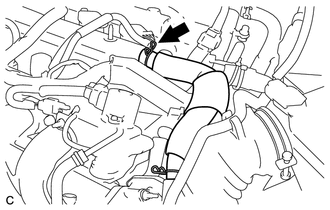
Connect the No. 2 ventilation hose to the cylinder head cover sub-assembly and slide the clip to secure it.
12261
10.CONNECT VENTILATION HOSE
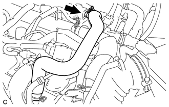
Connect the ventilation hose to the cylinder head cover sub-assembly and slide the clip to secure it.
11.INSPECT IGNITION TIMING
12.INSPECT FOR OIL LEAK
11212
13.INSTALL NO. 2 CYLINDER HEAD COVER