2NZ-FE ENGINE MECHANICAL VALVE CLEARANCE ADJUSTMENT
PROCEDURE

 11212
1.REMOVE NO. 2 CYLINDER HEAD COVER
11212
1.REMOVE NO. 2 CYLINDER HEAD COVER
19500D
2.REMOVE NO. 1 IGNITION COIL
12262
3.DISCONNECT NO. 2 VENTILATION HOSE
12261
4.DISCONNECT VENTILATION HOSE
11201
5.REMOVE CYLINDER HEAD COVER SUB-ASSEMBLY
11213
6.REMOVE CYLINDER HEAD COVER GASKET
7.SET NO. 1 CYLINDER TO TDC/COMPRESSION
8.CHECK VALVE CLEARANCE
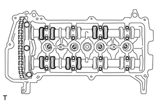
Check only the valves indicated.
Using a feeler gauge, measure the clearance between the valve lifter and camshaft.
- Standard Valve Clearance (Cold):
- Intake:
0.15 to 0.25 mm (0.00591 to 0.00984 in.)
- Exhaust:
0.25 to 0.35 mm (0.00984 to 0.0137 in.)
Record any out-of-specification valve clearance measurements. They will be used later to determine the required replacement valve lifters.
Turn the crankshaft 1 revolution (360°) to set the No. 4 cylinder to TDC / compression.
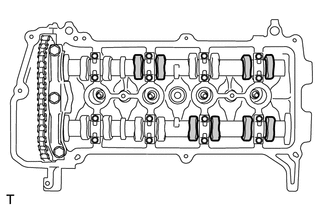
Check only the valves indicated.
Using a feeler gauge, measure the clearance between the valve lifter and camshaft.
- Standard Valve Clearance (Cold):
- Intake:
0.15 to 0.25 mm (0.00591 to 0.00984 in.)
- Exhaust:
0.25 to 0.35 mm (0.00984 to 0.0137 in.)
Record any out-of-specification valve clearance measurements. They will be used later to determine the required replacement valve lifters.
9.ADJUST VALVE CLEARANCE
Remove the 2 camshafts.
Click hereEngine / Hybrid System>2NZ-FE ENGINE MECHANICAL>CAMSHAFT>REMOVAL
Remove the valve lifters.
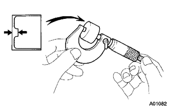
Using a micrometer, measure the thickness of the removed valve lifters.
Calculate the thickness of a new valve lifter so that the valve clearance comes within the specified values.
| A | Thickness of new valve lifter |
| B | Thickness of used valve lifter |
| C | Measured valve clearance |
- Valve Clearance:
- Intake:
A = B + (C - 0.20 mm (0.00787 in.))
- Exhaust:
A = B + (C - 0.30 mm (0.0118 in.))
| Example (Intake):
Measured intake valve clearance = 0.40 mm (0.0157 in.) 0.40 mm (0.0157 in.) - 0.20 mm (0.00787 in.) = 0.20 mm (0.00787 in.) (Measured - Specification = Excess clearance) Used lifter measurement = 5.250 mm (0.2067 in.) 0.20 mm (0.00787 in.) + 5.250 mm (0.2067 in.) = 5.450 mm (0.2146 in.) (Excess clearance + Used valve lifter = Ideal new valve lifter) Closest new valve lifter = 5.460 mm (0.2150 in.) Select No. 46 lifter |
- HINT:
- ·
Select a new valve lifter with a thickness as close to the calculated values as possible.
·Lifters are available in 35 sizes in increments of 0.020 mm (0.000787 in.), from 5.060 mm (0.1992 in.) to 5.740 mm (0.2260 in.).
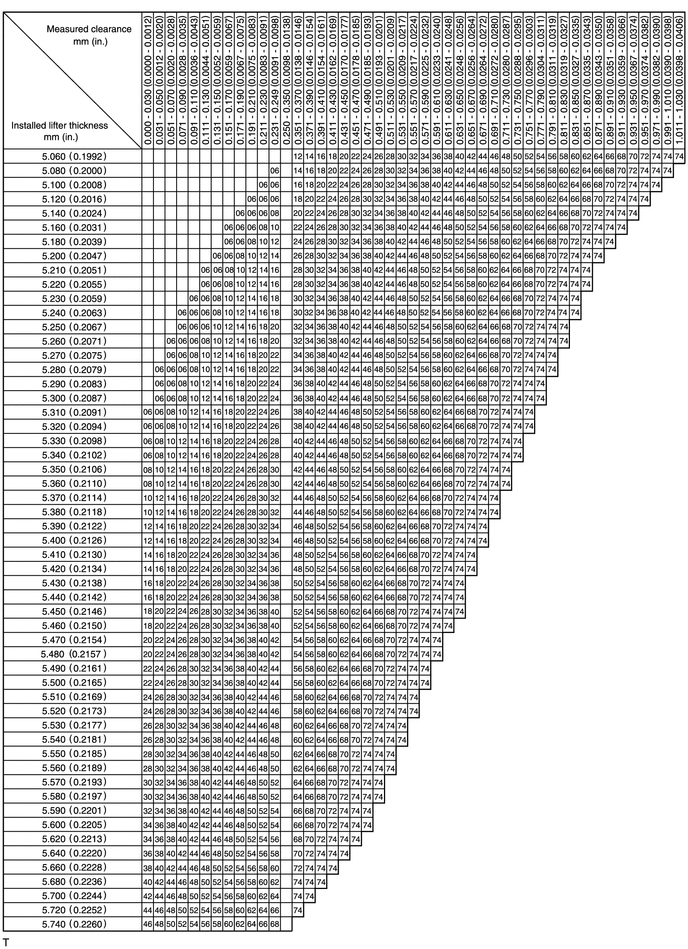
·Refer to the following Valve Lifter Selection Chart and New Lifter Thickness tables.
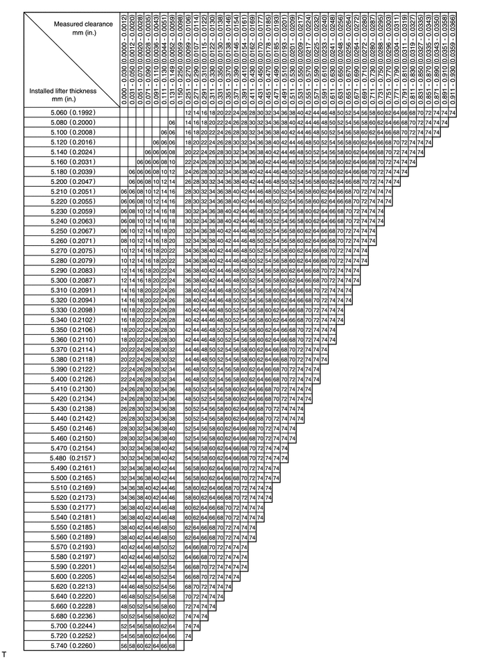
- Intake Valve Clearance (Cold):
0.15 to 0.25 mm (0.00591 to 0.00984 in.)
EXAMPLE:
The 5.250 mm (0.2067 in.) lifter is installed, and the measured clearance is 0.400 mm (0.0157 in.).
Replace the 5.250 mm (0.2067 in.) lifter with a new No. 46 lifter.
| Lifter No. | Thickness | Lifter No. | Thickness | Lifter No. | Thickness |
|---|---|---|---|---|---|
| 06 | 5.060 (0.1992) | 30 | 5.300 (0.2087) | 54 | 5.540 (0.2181) |
| 08 | 5.080 (0.2000) | 32 | 5.320 (0.2094) | 56 | 5.560 (0.2189) |
| 10 | 5.100 (0.2008) | 34 | 5.340 (0.2102) | 58 | 5.580 (0.2197) |
| 12 | 5.120 (0.2016) | 36 | 5.360 (0.2110) | 60 | 5.600 (0.2205) |
| 14 | 5.140 (0.2024) | 38 | 5.380 (0.2118) | 62 | 5.620 (0.2213) |
| 16 | 5.160 (0.2031) | 40 | 5.400 (0.2126) | 64 | 5.640 (0.2220) |
| 18 | 5.180 (0.2039) | 42 | 5.420 (0.2134) | 66 | 5.660 (0.2228) |
| 20 | 5.200 (0.2047) | 44 | 5.440 (0.2142) | 68 | 5.680 (0.2236) |
| 22 | 5.220 (0.2055) | 46 | 5.460 (0.2150) | 70 | 5.700 (0.2244) |
| 24 | 5.240 (0.2063) | 48 | 5.480 (0.2157) | 72 | 5.720 (0.2252) |
| 26 | 5.260 (0.2071) | 50 | 5.500 (0.2165) | 74 | 5.740 (0.2260) |
| 28 | 5.280 (0.2079) | 52 | 5.520 (0.2173) | - | - |
- Exhaust Valve Clearance (Cold):
0.25 to 0.35 mm (0.00984 to 0.0137 in.)
EXAMPLE:
The 5.340 mm (0.2102 in.) lifter is installed, and the measured clearance is 0.440 mm (0.0173 in.).
Replace the 5.340 mm (0.2102 in.) lifter with a new No. 48 lifter.
| Lifter No. | Thickness | Lifter No. | Thickness | Lifter No. | Thickness |
|---|---|---|---|---|---|
| 06 | 5.060 (0.1992) | 30 | 5.300 (0.2087) | 54 | 5.540 (0.2181) |
| 08 | 5.080 (0.2000) | 32 | 5.320 (0.2094) | 56 | 5.560 (0.2189) |
| 10 | 5.100 (0.2008) | 34 | 5.340 (0.2102) | 58 | 5.580 (0.2197) |
| 12 | 5.120 (0.2016) | 36 | 5.360 (0.2110) | 60 | 5.600 (0.2205) |
| 14 | 5.140 (0.2024) | 38 | 5.380 (0.2118) | 62 | 5.620 (0.2213) |
| 16 | 5.160 (0.2031) | 40 | 5.400 (0.2126) | 64 | 5.640 (0.2220) |
| 18 | 5.180 (0.2039) | 42 | 5.420 (0.2134) | 66 | 5.660 (0.2228) |
| 20 | 5.200 (0.2047) | 44 | 5.440 (0.2142) | 68 | 5.680 (0.2236) |
| 22 | 5.220 (0.2055) | 46 | 5.460 (0.2150) | 70 | 5.700 (0.2244) |
| 24 | 5.240 (0.2063) | 48 | 5.480 (0.2157) | 72 | 5.720 (0.2252) |
| 26 | 5.260 (0.2071) | 50 | 5.500 (0.2165) | 74 | 5.740 (0.2260) |
| 28 | 5.280 (0.2079) | 52 | 5.520 (0.2173) | - | - |
Install the valve lifters.
Install the 2 camshafts.
Click hereEngine / Hybrid System>2NZ-FE ENGINE MECHANICAL>CAMSHAFT>INSTALLATION
11213
10.INSTALL CYLINDER HEAD COVER GASKET
11201
11.INSTALL CYLINDER HEAD COVER SUB-ASSEMBLY
12261
12.CONNECT VENTILATION HOSE
12262
13.CONNECT NO. 2 VENTILATION HOSE
19500D
14.INSTALL NO. 1 IGNITION COIL
15.INSPECT FOR OIL LEAK
11212
16.INSTALL NO. 2 CYLINDER HEAD COVER