2NZ-FE ENGINE MECHANICAL REAR CRANKSHAFT OIL SEAL INSTALLATION
CAUTION / NOTICE / HINT
- NOTICE:
-
for Manual Transaxle:
-
When the manual transaxle assembly is removed, be sure to use a new clutch release with bearing cylinder assembly and new installation bolts. Removal of the manual transaxle assembly allows the compressed clutch release with bearing cylinder assembly to return to its original position, and dust could damage the seal of the clutch release with bearing cylinder assembly, possibly causing clutch fluid leaks.
PROCEDURE

 11401L
1.INSTALL REAR ENGINE OIL SEAL
11401L
1.INSTALL REAR ENGINE OIL SEAL
Using height adjustment attachments and plate lift attachments, place the engine assembly on a flat, level surface.
- NOTICE:
- ·
Using height adjustment attachments and plate lift attachments, place the engine assembly horizontally.
·Using an engine sling device and engine lift, secure the engine assembly before servicing.
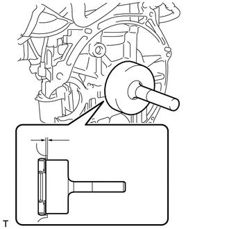
Apply MP grease to the lip of a new rear engine oil seal.
- SST
- 09223-56010
- NOTICE:
-
Keep the lip free from foreign matter.
Using SST and a hammer, tap in the rear engine oil seal until its surface is flush with the rear engine oil seal edge.
- NOTICE:
- ·
Wipe off excess grease from the crankshaft.
·Do not tap in the rear engine oil seal at an angle.
- HINT:
-
Rear engine oil seal tap in depth: 0 to -1.0 mm (0 to -0.0394 in.)
13405
2.INSTALL FLYWHEEL SUB-ASSEMBLY (for Manual Transaxle)
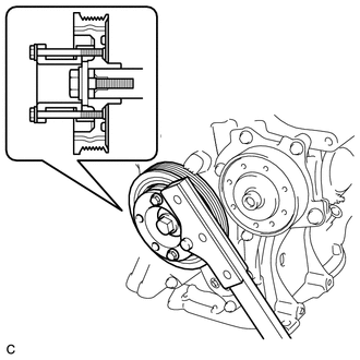
Using SST, hold the crankshaft damper sub-assembly.
- SST
- 09213-54015 09330-00021
Clean the bolts and bolt holes.
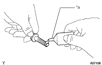
| *a | Adhesive |
Apply adhesive to 2 or 3 threads at the tip of each of the 6 bolts.
- Adhesive:
Toyota Genuine Adhesive 1324, Three Bond 1324 or equivalent
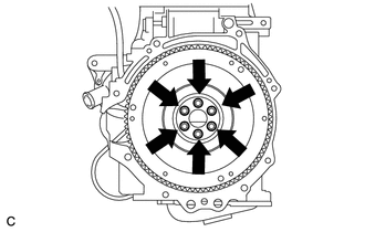
Install and uniformly tighten the 6 bolts in several steps in the sequence shown in the illustration.
- Torque:
- 49 N*m (500 kgf*cm, 36 ft.*lbf)
- NOTICE:
-
Do not start the engine for at least 1 hour after installing the flywheel sub-assembly.
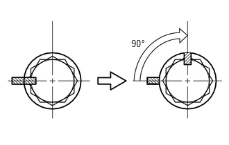

|
Paint Mark |
Mark the front of the bolts with paint.
Tighten the 6 bolts by 90° in the same order.
Check that the paint marks are now at a 90° angle to the front.
Check that the crankshaft turns smoothly.
32101
3.INSTALL DRIVE PLATE AND RING GEAR SUB-ASSEMBLY (for Automatic Transaxle)
Using SST, hold the crankshaft damper sub-assembly.
- SST
- 09213-54015 09330-00021
Clean the bolts and bolt holes.
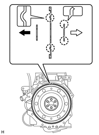
| *1 | Front Drive Plate Spacer (Reversible) |
| *2 | Rear Drive Plate Spacer |
| *3 | Drive Plate and Ring Gear Sub-assembly |

|
Engine Side |

|
Transaxle Side |
Install the front drive plate spacer, drive plate and ring gear sub-assembly and rear drive plate spacer to the crankshaft.
| *a | Adhesive |
Apply adhesive to 2 or 3 threads at the end of each of the 6 bolts.
- Adhesive:
Toyota Genuine Adhesive 1324, Three Bond 1324 or equivalent
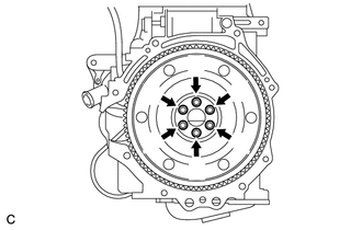
Install and uniformly tighten the 6 bolts in several steps in the sequence shown in the illustration.
- Torque:
- 88 N*m (897 kgf*cm, 65 ft.*lbf)
- NOTICE:
-
Do not start the engine for at least 1 hour after installing the drive plate and ring gear sub-assembly.
31250
4.INSTALL CLUTCH DISC ASSEMBLY (for Manual Transaxle)
30500
5.INSTALL AUTOMATIC TRANSAXLE ASSEMBLY (for Automatic Transaxle)