CLUTCH CLUTCH UNIT(for C50) INSTALLATION
PROCEDURE

 31250
1.INSTALL CLUTCH DISC ASSEMBLY
31250
1.INSTALL CLUTCH DISC ASSEMBLY
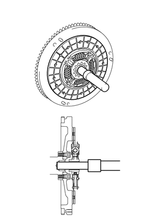
| *1 | Clutch Disc Assembly |
| *a | Flywheel Sub-assembly Side |
Insert SST into the clutch disc assembly, then insert them both into the flywheel sub-assembly.
- SST
- 09301-00210
- NOTICE:
-
Insert the clutch disc assembly in the correct direction.
31210
2.INSTALL CLUTCH COVER ASSEMBLY
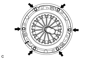
| *a | Temporarily Install |
| *b | Matchmark |
Align the matchmark on the clutch cover assembly with that on the flywheel sub-assembly.
Following the procedure shown in the illustration, tighten the 6 bolts in order, starting with the bolt located near the knock pin at the top.
- SST
- 09301-00210
- Torque:
- 19.1 N*m (195 kgf*cm, 14 ft.*lbf)
- HINT:
- ·
Following the order in the illustration, tighten the bolts evenly one at a time.
·Move SST up and down, right and left lightly after checking that the clutch disc assembly is in the center, and tighten the bolts.
31210
3.INSPECT AND ADJUST CLUTCH COVER ASSEMBLY
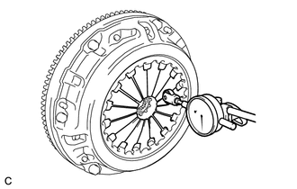
Using a dial indicator with a roller instrument, check the diaphragm spring tip alignment.
- Maximum Non-alignment:
0.5 mm (0.0197 in.)
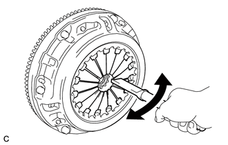
If the alignment is not as specified, using SST, adjust the diaphragm spring tip alignment.
- SST
- 09333-00013
31236B
4.INSTALL RELEASE FORK SUPPORT
Install the release fork support to the manual transaxle assembly.
- Torque:
- 36.8 N*m (375 kgf*cm, 27 ft.*lbf)
31126
5.INSTALL CLUTCH RELEASE FORK BOOT
Install the clutch release fork boot to the manual transaxle assembly.
31232A
6.INSTALL RELEASE BEARING HUB CLIP
Install the release bearing hub clip to the clutch release bearing assembly.
31204
7.INSTALL CLUTCH RELEASE FORK SUB-ASSEMBLY
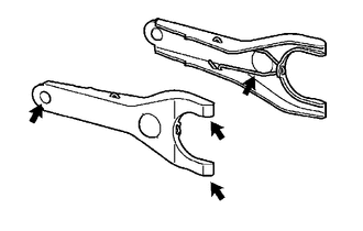

|
Release Hub Grease |
Apply release hub grease to the contact surfaces of the clutch release fork sub-assembly and clutch release bearing assembly, clutch release fork sub-assembly and release cylinder push rod, and clutch release fork sub-assembly and release fork support.
- Grease:
Toyota Genuine Release Hub Grease or equivalent
Install the clutch release fork sub-assembly with the clutch release bearing assembly to the manual transaxle assembly.
31230
8.INSTALL CLUTCH RELEASE BEARING ASSEMBLY
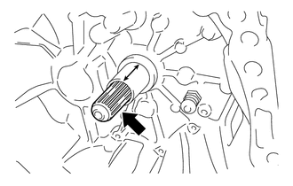
|
|
Clutch Spline Grease |
Apply clutch spline grease to the input shaft splines.
- NOTICE:
-
Do not apply grease to portion (A) shown in the illustration.
- Grease:
Toyota Genuine Clutch Spline Grease or equivalent
Install the clutch release bearing assembly with the clutch release fork sub-assembly to the manual transaxle assembly.
- NOTICE:
-
After the installation, move the clutch release fork sub-assembly forward and backward to check that the clutch release bearing assembly slides smoothly.
30300
9.INSTALL MANUAL TRANSAXLE ASSEMBLY