2NZ-FE FUEL FUEL INJECTOR INSTALLATION
PROCEDURE

 23250
1.INSTALL FUEL INJECTOR ASSEMBLY
23250
1.INSTALL FUEL INJECTOR ASSEMBLY
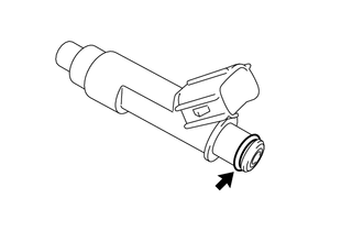
Apply a light coat of gasoline or spindle oil to new O-rings, and then install one onto each fuel injector assembly.
Apply a light coat of gasoline or spindle oil where the fuel delivery pipe sub-assembly contacts each O-ring.
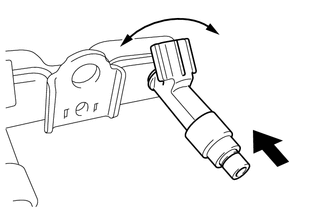
While turning the fuel injector assembly left and right, install it onto the fuel delivery pipe sub-assembly.
- NOTICE:
- ·
Do not damage the fuel injector assembly and O-ring.
·Do not twist the O-ring.
·After installing each fuel injector assembly, check that it turns smoothly. If not, replace the O-ring with a new one.
- HINT:
-
Use the same procedure to install the other fuel injector assemblies.
23291
2.INSTALL INJECTOR VIBRATION INSULATOR
Install 4 new injector vibration insulators to the cylinder head sub-assembly.
23807V
3.INSTALL NO. 1 DELIVERY PIPE SPACER
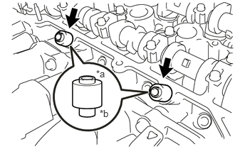
| *a | Fuel Delivery Pipe Sub-assembly Side |
| *b | Cylinder Head Sub-assembly Side |
Install the 2 No. 1 delivery pipe spacers onto the cylinder head sub-assembly.
- NOTICE:
-
Install the No. 1 delivery pipe spacers in the correct direction.
23807
4.INSTALL FUEL DELIVERY PIPE SUB-ASSEMBLY
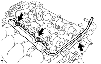
Temporarily install the fuel delivery pipe sub-assembly with the 4 fuel injector assemblies with the 3 bolts.
- NOTICE:
- ·
Do not drop the fuel injector assemblies when installing the fuel delivery pipe sub-assembly.
·After installing the fuel delivery pipe sub-assembly, check that the fuel injector assemblies turn smoothly.
Tighten the 2 bolts (A).
- Torque:
- 21 N*m (214 kgf*cm, 15 ft.*lbf)
Tighten the bolt (B).
- Torque:
- 10 N*m (102 kgf*cm, 7 ft.*lbf)
23901
5.CONNECT FUEL TUBE SUB-ASSEMBLY
- NOTICE:
-
Check if there is any damage or foreign matter on the connecting parts of the fuel lines.
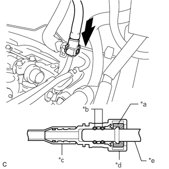
| *a | Retainer |
| *b | O-ring |
| *c | Nylon Tube |
| *d | Fuel Tube Connector |
| *e | Fuel Pipe |

|
Push |
Connect the fuel tube sub-assembly to the fuel delivery pipe sub-assembly.
Align the fuel tube connector with the fuel pipe, and push them together until the fuel tube connector makes a "click" sound. If it is difficult to push the fuel pipe into the fuel tube connector, apply a small amount of clean engine oil to the tip of the fuel pipe and reinsert it.
After connecting the fuel lines, check that the fuel pipe and fuel tube connector are securely connected by pulling on them.
Install the No. 1 fuel pipe clamp.
11213
6.INSTALL CYLINDER HEAD COVER GASKET
11201
7.INSTALL CYLINDER HEAD COVER SUB-ASSEMBLY
82121
8.CONNECT ENGINE WIRE
Engage the 2 clamps to connect the engine wire to the 2 wire harness clamp brackets.
Connect the 4 fuel injector assembly connectors.
12262
9.CONNECT NO. 2 VENTILATION HOSE
12261
10.CONNECT VENTILATION HOSE
19500D
11.INSTALL NO. 1 IGNITION COIL
12.CONNECT CABLE TO NEGATIVE BATTERY TERMINAL
- NOTICE:
-
When disconnecting the cable, some systems need to be initialized after the cable is reconnected.
-
Click hereGeneral>INTRODUCTION>REPAIR INSTRUCTION>INITIALIZATION
13.INSPECT FOR FUEL LEAK
11212
14.INSTALL NO. 2 CYLINDER HEAD COVER