2NZ-FE ENGINE MECHANICAL CYLINDER HEAD GASKET INSTALLATION
PROCEDURE

 11101A
1.INSPECT CYLINDER HEAD SET BOLT
11101A
1.INSPECT CYLINDER HEAD SET BOLT
11115
2.INSTALL CYLINDER HEAD GASKET
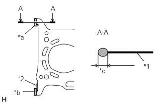
| *1 | Cylinder Head Gasket |
| *2 | No. 1 Chain Vibration Damper |
| *a | Apply enough seal packing so that it will spread to the inner side |
| *b | Apply enough seal packing so that it will spread onto the No. 1 Chain Vibration Damper |
| *c | 4.5 to 5.5 mm (0.177 to 0.217 in.) |

|
Seal Packing Black |
Apply seal packing to a new cylinder head gasket in the locations shown in the illustration.
- Seal Packing:
Toyota Genuine Seal Packing Black, Three Bond 1207B or equivalent
- NOTICE:
-
Remove any oil from the cylinder block sub-assembly.
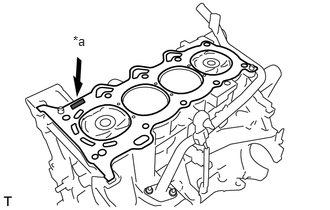
| *a | Lot No. |
Place the cylinder head gasket on the cylinder block sub-assembly with the Lot No. stamp facing upward.
- NOTICE:
- ·
Remove any oil from the contact surfaces.
·Check the mounting orientation of the cylinder head gasket.
·Place the cylinder head sub-assembly on the cylinder block sub-assembly gently in order not to damage the cylinder head gasket.
11101
3.INSTALL CYLINDER HEAD SUB-ASSEMBLY
- HINT:
-
The cylinder head set bolts are tightened in 3 progressive steps.
Place the cylinder head sub-assembly on the cylinder block sub-assembly.
- NOTICE:
- ·
Make sure that no oil is on the contact surface of the cylinder head sub-assembly.
·Place the cylinder head sub-assembly on the cylinder block sub-assembly gently in order not to damage the cylinder head gasket with the bottom part of the cylinder head sub-assembly.
Install the 10 plate washers to the 10 cylinder head set bolts.
Apply a light coat of engine oil to the threads and under the heads of the 10 cylinder head set bolts.
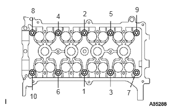
Step 1:
Using an 8 mm bi-hexagon wrench, install and uniformly tighten the 10 cylinder head set bolts in several steps, in the order shown in the illustration.
- Torque:
- 29.4 N*m (300 kgf*cm, 22 ft.*lbf)
- NOTICE:
-
Do not drop the plate washers into the cylinder head sub-assembly.

| *a | Paint Mark |
Step 2:
Mark each cylinder head set bolt head with paint as shown in the illustration.
Tighten the cylinder head set bolts 90° in the order shown in step 1.
Step 3:
Tighten the cylinder head set bolts another 90° in the order shown in step 1.
Check that the paint marks are now at a 180° angle to the front.
Wipe off any excess seal packing that seeped out.
13511
4.INSTALL CAMSHAFT
13512
5.INSTALL NO. 2 CAMSHAFT
13506
6.INSTALL CHAIN SUB-ASSEMBLY
13561
7.INSTALL NO. 1 CHAIN VIBRATION DAMPER
13559
8.INSTALL CHAIN TENSIONER SLIPPER
13540
9.INSTALL NO. 1 CHAIN TENSIONER ASSEMBLY
44763A
10.INSTALL NO. 1 HOSE TO HOSE TUBE
Install the No. 1 hose to hose tube with the 2 bolts.
- Torque:
- 9.0 N*m (92 kgf*cm, 80 in.*lbf)
16268
11.INSTALL NO. 1 WATER BY-PASS PIPE
Install a new gasket and the No. 1 water by-pass pipe with the 2 bolts and 2 nuts.
- Torque:
- 9.0 N*m (92 kgf*cm, 80 in.*lbf)
87246
12.CONNECT OUTLET HEATER WATER HOSE
Connect the outlet heater water hose to the No. 1 water by-pass pipe and slide the clip to secure it.
87245
13.CONNECT INLET HEATER WATER HOSE
Connect the inlet heater water hose to the cylinder head sub-assembly and slide the clip to secure it.
44774E
14.CONNECT VACUUM BRAKE HOSE
Connect the vacuum brake hose to the No. 1 hose to hose tube and slide the clip to secure it.
16571C
15.CONNECT NO. 1 RADIATOR HOSE
44774
16.CONNECT UNION TO CONNECTOR TUBE HOSE
23250
17.INSTALL FUEL INJECTOR ASSEMBLY
23291
18.INSTALL INJECTOR VIBRATION INSULATOR
23807V
19.INSTALL NO. 1 DELIVERY PIPE SPACER
23807
20.INSTALL FUEL DELIVERY PIPE SUB-ASSEMBLY
23901
21.CONNECT FUEL TUBE SUB-ASSEMBLY
22.CONNECT WIRE HARNESS
Connect the wire harness with the 2 bolts.
- Torque:
- 8.4 N*m (86 kgf*cm, 6 ft.*lbf)
Connect the engine coolant temperature sensor connector.
Connect the camshaft position sensor connector.
Engage the 2 clamps to connect the engine wire to the 2 wire harness clamp brackets.
Connect the 4 fuel injector assembly connectors.
15100
23.INSTALL OIL PUMP ASSEMBLY
17141
24.INSTALL EXHAUST MANIFOLD
17111
25.INSTALL INTAKE MANIFOLD
27020
26.INSTALL GENERATOR ASSEMBLY
27.INSPECT IGNITION TIMING
28.INSPECT ENGINE IDLING SPEED
29.INSPECT CO/HC
30.INSPECT FOR FUEL LEAK