2NZ-FE ENGINE MECHANICAL ENGINE UNIT INSPECTION
PROCEDURE

 13506
1.INSPECT CHAIN SUB-ASSEMBLY
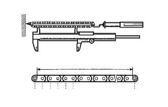
| *a | Measuring Area |
Using a spring scale and vernier caliper, apply 140 N (14.3 kgf, 31.5 lbf) to the chain sub-assembly and measure its length.
- Maximum Chain Elongation:
123.2 mm (4.85 in.)
- HINT:
- ·
Perform the same measurement at 3 or more random places and calculate the average length.
·If the chain elongation is greater than the maximum, replace the chain sub-assembly.

 13540
2.INSPECT NO. 1 CHAIN TENSIONER ASSEMBLY
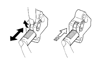
| *a | Ratchet Pawl |
| *b | Plunger |
Check that the plunger moves smoothly when the ratchet pawl is raised with your finger.
Release the ratchet pawl and check that the plunger is locked in place by the ratchet pawl and does not move when pushed with your finger.

 13559
3.INSPECT CHAIN TENSIONER SLIPPER
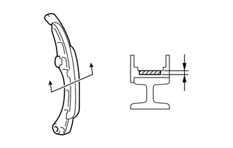
Using a vernier caliper, measure the chain tensioner slipper wear.
- Maximum Wear:
1.0 mm (0.0394 in.)
- HINT:
-
If the wear is greater than the maximum, replace the chain tensioner slipper.

 13561
4.INSPECT NO. 1 CHAIN VIBRATION DAMPER
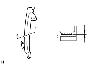
Using a vernier caliper, measure the No. 1 chain vibration damper wear.
- Maximum Wear:
1.0 mm (0.0394 in.)
- HINT:
-
If the wear is greater than the maximum, replace the No. 1 chain vibration damper.

 13511
5.INSPECT CAMSHAFT
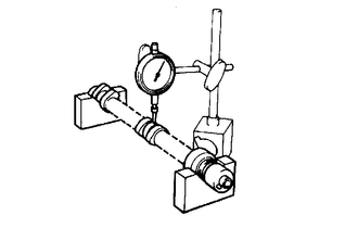
Inspect the camshaft for runout.
Place the camshaft on V-blocks.
Using a dial indicator, measure the runout at the center journal.
- Maximum Runout:
0.03 mm (0.00118 in.)
- HINT:
-
If the runout is greater than the maximum, replace the camshaft.
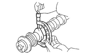
Inspect the cam lobes.
Using a micrometer, measure the cam lobe height.
- Standard Cam Lobe Height:
44.617 to 44.717 mm (1.7566 to 1.7605 in.)
- Minimum Cam Lobe Height:
43.16 mm (1.6992 in.)
- HINT:
-
If the cam lobe height is less than the minimum, replace the camshaft.
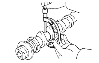
Inspect the camshaft journals.
Using a micrometer, measure the journal diameter.
- Standard Journal Diameter:
Journal Specified Condition No. 1 journal 34.449 to 34.465 mm (1.3563 to 1.3569 in.) Other journals 22.949 to 22.965 mm (0.9036 to 0.9041 in.)
- HINT:
-
If the journal diameter is not as specified, check the oil clearance.

 13512
6.INSPECT NO. 2 CAMSHAFT
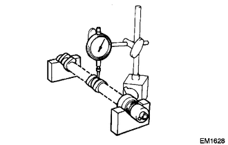
Inspect the No. 2 camshaft for runout.
Place the No. 2 camshaft on V-blocks.
Using a dial indicator, measure the runout at the center journal.
- Maximum Runout:
0.03 mm (0.00118 in.)
- HINT:
-
If the runout is greater than the maximum, replace the No. 2 camshaft.
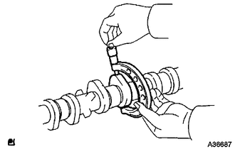
Inspect the cam lobes.
Using a micrometer, measure the cam lobe height.
- Standard Cam Lobe Height:
44.046 to 44.146 mm (1.7341 to 1.7380 in.)
- Minimum Cam Lobe Height:
43.90 mm (1.7283 in.)
- HINT:
-
If the cam lobe height is less than the minimum, replace the No. 2 camshaft.
Inspect the No. 2 camshaft journals.
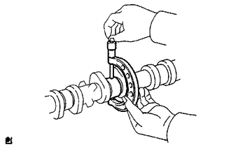
Using a micrometer, measure the journal diameter.
- Standard Journal Diameter:
Journal Specified Condition No. 1 journal 34.449 to 34.465 mm (1.3563 to 1.3569 in.) Other journals 22.949 to 22.965 mm (0.9036 to 0.9041 in.)
- HINT:
-
If the journal diameter is not as specified, check the oil clearance.

 13050
7.INSPECT CAMSHAFT TIMING GEAR ASSEMBLY
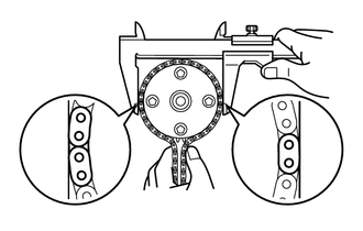
Check the gear diameter (with chain sub-assembly).
Wrap the chain sub-assembly around the camshaft timing gear assembly.
Using a vernier caliper, measure the diameter of the camshaft timing gear assembly with the chain sub-assembly.
- Minimum Gear Diameter (with chain sub-assembly):
96.2 mm (3.787 in.)
- NOTICE:
-
Make sure that the vernier caliper is in contact with the chain link when measuring.
- HINT:
-
If the diameter is less than the minimum, replace the camshaft timing gear assembly.
Install the camshaft.
Click hereEngine / Hybrid System>2NZ-FE ENGINE MECHANICAL>ENGINE UNIT>REASSEMBLY
Check the lock of camshaft timing gear assembly.
Secure the camshaft in a vise, and confirm that the camshaft timing gear assembly is locked.
- NOTICE:
-
Do not damage the camshaft.
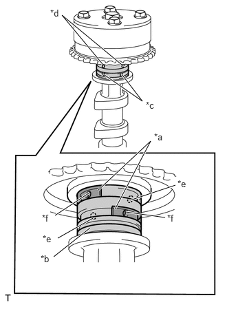
| *a | Rubber Piece |
| *b | Vinyl Tape |
| *c | Advance Side Path |
| *d | Retard Side Path |
| *e | Open |
| *f | Closed |
Release the lock pin.
Cover the 4 oil paths of the cam journal with vinyl tape as shown in the illustration.
- HINT:
-
One of the 2 grooves located on the cam journal is for retarding cam timing (upper) and the other is for advancing cam timing (lower). Each groove has 2 oil paths. Plug one of the oil paths of each groove with a rubber piece before wrapping the cam journal with the vinyl tape.
Prick a hole in the vinyl tape of the advance side path and retard side path on opposite side of the camshaft.
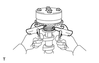
| *a | Retard Side Path |
| *b | Advance Side Path |
Apply compressed air of approximately 150 kPa (1.5 kgf/cm2, 22 psi) pressure into the 2 open paths (the advance side path and retard side path).
- NOTICE:
-
Cover the paths with a piece of cloth to prevent oil from spraying.
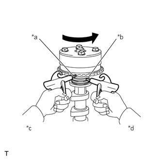
| *a | Retard Side Path |
| *b | Advance Side Path |
| *c | Decompress |
| *d | Hold Pressure |
Confirm that the camshaft timing gear assembly turns in the advance direction when reducing the air pressure applied to the retard side path.
- HINT:
-
The lock pin is released and the camshaft timing gear assembly turns in the advance direction.
When the camshaft timing gear assembly reaches the most advanced position, release the air pressure on the retard side path, and then release the air pressure on the advance side path.
- NOTICE:
-
Be sure to release the air pressure from the retard side path first. If the air pressure of the advance side path is released first, the camshaft timing gear assembly may abruptly shift in the retard direction and break the lock pin or other parts.
Check for smooth rotation.
Turn the camshaft timing sprocket assembly within its movable range 2 or 3 times, but do not turn it to the most retarded position. Make sure that the sprocket turns smoothly.
- Standard:
Smooth movable range is approximately 22.5°
- NOTICE:
-
Do not use air pressure to perform the smooth operation check.
- HINT:
-
If necessary, replace the camshaft timing gear assembly.
Check the lock in the most retarded position.
Confirm that the camshaft timing gear assembly locks at the most retarded position.
Remove the camshaft.
Click hereEngine / Hybrid System>2NZ-FE ENGINE MECHANICAL>ENGINE UNIT>DISASSEMBLY

 13523
8.INSPECT CAMSHAFT TIMING SPROCKET
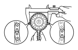
Wrap the chain sub-assembly around the camshaft timing sprocket.
Using a vernier caliper, measure the diameter of the camshaft timing sprocket with the chain sub-assembly.
- Minimum Gear Diameter (with chain sub-assembly):
96.2 mm (3.787 in.)
- NOTICE:
-
Make sure that the vernier caliper is in contact with the chain link when measuring.
- HINT:
-
If the diameter is less than the minimum, replace the camshaft timing sprocket.

 11101A
9.INSPECT CYLINDER HEAD SET BOLT
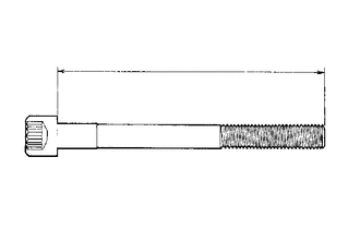
| *a | Measurement Length |
Using a vernier caliper, measure the length of the cylinder head set bolt from the seat to the end.
- Standard Bolt Length:
142.8 to 144.2 mm (5.6220 to 5.6772 in.)
- Maximum Bolt Length:
147.1 mm (5.7913 in.)
- HINT:
-
If the bolt length is greater than the maximum, replace the cylinder head set bolt.