STEERING COLUMN STEERING COLUMN ASSEMBLY INSTALLATION
PROCEDURE

 1.INSPECT STEERING COLUMN ASSEMBLY
2.INSTALL STEERING COLUMN ASSEMBLY
Install the steering column assembly with the bolt and 2 nuts.
- Torque:
- Bolt : 36 N*m (367 kgf*cm, 27 ft.*lbf)
- Nut : 25 N*m (255 kgf*cm, 18 ft.*lbf)
- NOTICE:
-
Make sure that the wire harness is not interfering with the steering column assembly.
Connect each connector and engage each wire harness clamp to the steering column assembly.
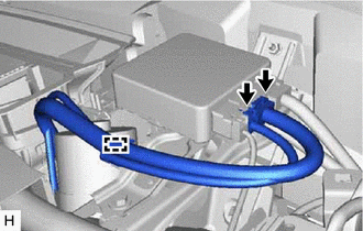
Engage the clamp.
Connect the 2 connectors.
45260
3.INSTALL NO. 2 STEERING INTERMEDIATE SHAFT ASSEMBLY
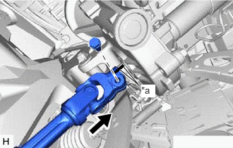
| *a | Matchmark |
Align the matchmarks on the No. 2 steering intermediate shaft assembly and steering column assembly.
Install the No. 2 steering intermediate shaft assembly to the steering column assembly.
Install a new bolt.
- Torque:
- 35 N*m (357 kgf*cm, 26 ft.*lbf)
55106
4.INSTALL BRAKE PEDAL SUPPORT ASSEMBLY
55045
5.INSTALL LOWER INSTRUMENT PANEL FINISH PANEL SUB-ASSEMBLY
55606
6.INSTALL NO. 1 INSTRUMENT PANEL UNDER COVER SUB-ASSEMBLY
55447C
7.INSTALL NO. 2 SWITCH HOLE BASE (w/o Smart Entry and Start System)
55446A
8.INSTALL NO. 1 SWITCH HOLE BASE
55545
9.INSTALL FUSE BOX OPENING COVER
10.INSTALL UPPER INSTRUMENT PANEL ASSEMBLY
45260
11.CONNECT NO. 2 STEERING INTERMEDIATE SHAFT ASSEMBLY
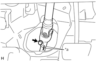
| *a | Matchmark |
Align the matchmarks on the No. 2 steering intermediate shaft assembly and steering intermediate shaft assembly.
Connect the No. 2 steering intermediate shaft assembly to the steering intermediate shaft assembly.
Install a new bolt.
- Torque:
- 35 N*m (357 kgf*cm, 26 ft.*lbf)
45259A
12.INSTALL COLUMN HOLE COVER SILENCER SHEET
Install the column hole cover silencer sheet with the 2 clips.
Install the floor carpet.
13.INSTALL TURN SIGNAL SWITCH ASSEMBLY WITH SPIRAL CABLE SUB-ASSEMBLY
- NOTICE:
- w/ VSC:
- ·
Do not replace the spiral cable with sensor sub-assembly with the battery connected and the ignition switch ON.
·Do not rotate the spiral cable with sensor sub-assembly without the steering wheel assembly with the battery connected and the ignition switch ON.
·Ensure that the steering wheel assembly is installed and aligned straight when inspecting the steering sensor.
·Do not remove the steering sensor from the spiral cable.
Using pliers, expand the clamp.
While holding the clamp expanded, install the turn signal switch assembly with spiral cable sub-assembly to the steering column assembly and engage the claw.
Return the clamp to its original position.
Connect each connector to the turn signal switch assembly with spiral cable sub-assembly.
45286B
14.INSTALL UPPER STEERING COLUMN COVER
Engage the 2 claws to install the upper steering column cover.
45287
15.INSTALL LOWER STEERING COLUMN COVER
Engage the 5 claws to install the lower steering column cover.
Install the 2 screws.
16.ALIGN FRONT WHEELS FACING STRAIGHT AHEAD
17.INSPECT AND ADJUST SPIRAL CABLE
18.INSTALL STEERING WHEEL ASSEMBLY
19.CHECK STEERING WHEEL CENTER POINT
45130
20.INSTALL HORN BUTTON ASSEMBLY
21. PERFORM CALIBRATION OF TORQUE SENSOR ZERO POINT