BRAKE SYSTEM (OTHER) BRAKE PEDAL INSTALLATION
PROCEDURE

 1.INSTALL BRAKE PEDAL SUPPORT ASSEMBLY
Install the nut to the brake pedal support assembly.
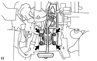
Install the brake pedal support assembly with the 4 nuts.
- Torque:
- 12.7 N*m (130 kgf*cm, 9 ft.*lbf)
- NOTICE:
-
Tighten the 4 nuts in the order shown in the illustration.
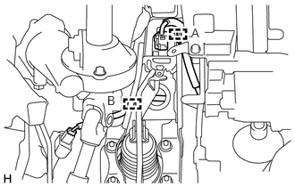
Engage the clamp (A) to install the wire harness to the brake pedal support assembly.
for Manual Transaxle:
Engage the clamp (B) to install the wire harness to the brake pedal support assembly.
Install the brake pedal support assembly to the instrument panel reinforcement assembly with the bolt.
- Torque:
- 23.6 N*m (241 kgf*cm, 17 ft.*lbf)
47264A
2.INSTALL PUSH ROD PIN

|
Lithium Soap Base Glycol Grease |
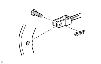
Apply lithium soap base glycol grease to the push rod pin and installation hole of the brake pedal support assembly.
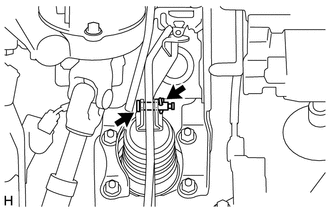
Connect the brake master cylinder push rod clevis to the brake pedal support assembly with the push rod pin as shown in the illustration and install a new clip.
- NOTICE:
-
Install the push rod pin in the correct direction.
47101A
3.INSTALL BRAKE PEDAL RETURN SPRING
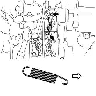

|
Front |
Install the brake pedal return spring to the brake pedal support assembly and push rod pin.
- NOTICE:
-
Install the brake pedal return spring in the correct direction as shown in the illustration.
84345
4.INSTALL STOP LIGHT SWITCH MOUNTING ADJUSTER
84340
5.INSTALL STOP LIGHT SWITCH ASSEMBLY
55606
6.INSTALL NO. 1 INSTRUMENT PANEL UNDER COVER SUB-ASSEMBLY
83100
7.INSTALL COMBINATION METER ASSEMBLY
8.INSPECT AND ADJUST BRAKE PEDAL