POWER ASSIST SYSTEMS POWER STEERING SYSTEM CALIBRATION
TORQUE SENSOR ZERO POINT CALIBRATION (USING GTS)
- NOTICE:
-
Perform torque sensor zero point calibration if any of the following conditions occur:
- ·
The power steering ECU assembly has been replaced.
·The electric power steering column sub-assembly has been replaced.
·There is a difference in steering effort between turning left and right.
Perform inspection before calibration.
Turn the ignition switch off.
Connect the GTS to the DLC3.
Turn the ignition switch to ON.
Turn the GTS on.
Calibrate the power steering ECU assembly. Enter the following menus: Chassis / EMPS / Data List.
Check the values by referring to the table below.
- Chassis > EMPS > Data List
-
Tester Display Measurement Item Range Normal Condition Diagnostic Note IG Power Supply IG power source voltage Min.: 0.0000 V
Max.: 20.1531 V8 to 16 V Ignition switch ON
- Chassis > EMPS > Data List
-
Tester Display IG Power Supply - 50003 142 11
- Standard Voltage:
8 to 16 V
- NOTICE:
-
If the IG power supply voltage is 8 V or less, calibration cannot be performed. In this case, charge or replace the battery, and then perform calibration.
Perform torque sensor zero point calibration.
- NOTICE:
-
If DTC C1516 (Torque Sensor Zero Point Adjustment Incomplete) is stored, the torque sensor zero point cannot be calibrated. Clear the DTCs before starting calibration.
Set the steering wheel to the center point and align the front wheels straight ahead.
Turn the ignition switch off.
Connect the GTS to the DLC3.
Turn the ignition switch to ON.
Turn the GTS on.
Enter the following menus: Chassis / EMPS / Utility / Torque Sensor Adjustment.
- Chassis > EMPS > Utility
-
Tester Display Torque Sensor Adjustment - 50005 142 224
- NOTICE:
- ·
Do not turn the steering wheel sharply.
·Do not touch the steering wheel during torque sensor zero point calibration (for 3 seconds).
Check for DTCs.
Click hereSteering>POWER ASSIST SYSTEMS>POWER STEERING SYSTEM>DTC CHECK / CLEAR
- Chassis > EMPS > Trouble Codes
- 50001 142
- NOTICE:
-
If DTC C1515, C1516, C1534 or C1581 is output, perform troubleshooting for the corresponding DTC.
- Result:
Result See Procedure DTC C1515 is output. (  )
)
DTC C1516 is output. ( )
DTC C1534 is output. ( )
DTC C1581 is output. ( )
TORQUE SENSOR ZERO POINT CALIBRATION (USING SST CHECK WIRE)
- NOTICE:
-
Perform torque sensor zero point calibration if any of the following conditions occur:
- ·
The power steering ECU assembly has been replaced.
·The electric power steering column sub-assembly has been replaced.
·There is a difference in steering effort between turning left and right.
Check for DTCs.
Check for DTCs.
Click hereSteering>POWER ASSIST SYSTEMS>POWER STEERING SYSTEM>DTC CHECK / CLEAR
- NOTICE:
- ·
If DTC 16 (Torque Sensor Zero Point Adjustment Incomplete) is stored, the torque sensor zero point cannot be calibrated. Clear the DTCs before starting calibration.
·If DTCs other than 16 is output, refer to Diagnostic Trouble Code Chart.
Click hereSteering>POWER ASSIST SYSTEMS>POWER STEERING SYSTEM>DIAGNOSTIC TROUBLE CODE CHART
Perform pre-calibration check.
Turn the ignition switch off.
Disconnect the E40 power steering ECU assembly connector.
Turn the ignition switch to ON.
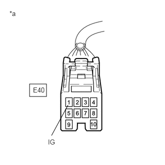
| *a | Front view of wire harness connector
(to Power Steering ECU Assembly) |
Measure the voltage according to the value(s) in the table below.
- Standard Voltage:
Tester Connection Condition Specified Condition E40-1 (IG) - Body ground Ignition switch ON 8 to 16 V
- NOTICE:
-
If the IG power supply voltage is 8 V or less, calibration cannot be performed. In this case, charge or replace the battery, and then perform calibration.
Turn the ignition switch off.
Reconnect the E40 power steering ECU assembly connector.
Clear sensor calibration value.
Set the steering wheel to the center point and align the front wheels straight ahead.
Turn the ignition switch off.
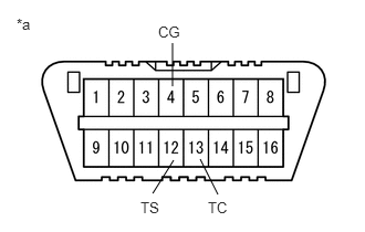
| *a | DLC3 |
Using SST, connect terminals 12 (TS) and 4 (CG) of the DLC3.
- SST
- 09843-18040
- NOTICE:
-
Connect the terminals to the correct positions to avoid a malfunction.
Turn the ignition switch to ON and then connect and disconnect terminals 13 (TC) and 4 (CG) at least 20 times in 20 seconds.

| *a | EPS Warning Light |
Check that the EPS warning light blinks and then remains illuminated.
- HINT:
-
The EPS warning light illumination indicates that DTC 15 has been stored.
Turn the ignition switch off.
- NOTICE:
-
After clearing the sensor calibration value, zero point calibration cannot be performed if the ignition switch is ON.
Perform torque sensor zero point calibration.
- NOTICE:
-
As torque sensor zero point calibration cannot be performed if DTC 15 has not been stored, be sure to perform sensor calibration value erasure before performing torque sensor zero point calibration.
Set the steering wheel to the center point and align the front wheels straight ahead.
Turn the ignition switch off.
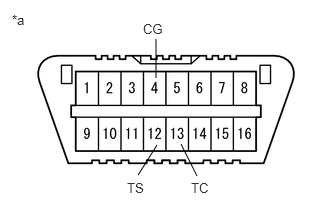
| *a | DLC3 |
Using SST, connect terminals 12 (TS) and 4 (CG) of the DLC3.
- SST
- 09843-18040
Turn the ignition switch to ON and then connect terminals 13 (TC) and 4 (CG).
- NOTICE:
-
Do not touch the steering wheel during calibration (for 3 seconds).
- HINT:
-
The EPS warning light remains illuminated even after calibration has completed.
ASSIST MAP WRITING (USING GTS)
- NOTICE:
-
Perform assist map writing if the following condition occurs:
-
The power steering ECU assembly has been replaced.
Turn the ignition switch off.
Connect the GTS to the DLC3.
Turn the ignition switch to ON.
Turn the GTS on.
Enter the following menus: Chassis / EMPS / Utility / Signal Check.
- Chassis > EMPS > Utility
-
Tester Display Signal Check - 50005 142 3
- HINT:
- ·
Follow the instructions on the GTS to perform Signal Check.
·With DTC C1581 output, performing Signal Check will cause the power steering ECU assembly to enter Signal Check and the assist map will be written automatically.
Wait for at least 5 seconds.
Check for DTCs.
Click hereSteering>POWER ASSIST SYSTEMS>POWER STEERING SYSTEM>DTC CHECK / CLEAR
- Chassis > EMPS > Trouble Codes
- 50001 142
- HINT:
-
After writing the assist map, if DTC C1581 is output, perform the troubleshooting procedure for DTC C1581.
-
Click hereSteering>POWER ASSIST SYSTEMS>POWER STEERING SYSTEM>C1581
ASSIST MAP WRITING (USING SST CHECK WIRE)
- NOTICE:
-
Perform assist map writing if the following condition occurs:
-
The power steering ECU assembly has been replaced.
- HINT:
-
If DTC 81 is output after torque sensor zero point calibration, perform assist map writing.
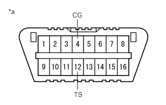
| *a | DLC3 |
Turn the ignition switch off.
Using SST, connect terminals 12 (TS) and 4 (CG) of the DLC3.
- SST
- 09843-18040
- NOTICE:
-
Connect the terminals properly to avoid a malfunction.
Turn the ignition switch to ON.
Wait for 5 seconds or more.
Check for DTCs.
Click hereSteering>POWER ASSIST SYSTEMS>POWER STEERING SYSTEM>DTC CHECK / CLEAR
- HINT:
-
After writing the assist map, if DTC 81 is output, perform the troubleshooting procedure for DTC 81.
-
Click hereSteering>POWER ASSIST SYSTEMS>POWER STEERING SYSTEM>C1581