REAR SUSPENSION REAR AXLE BEAM REMOVAL
PROCEDURE

 1.REMOVE REAR WHEELS
89408B
2.REMOVE REAR HEIGHT CONTROL SENSOR SUB-ASSEMBLY (w/ Height Control Sensor)
58804A
3.REMOVE UPPER CONSOLE PANEL SUB-ASSEMBLY
46441A
4.LOOSEN NO. 2 WIRE ADJUSTING NUT
89516D
5.SEPARATE SKID CONTROL SENSOR WIRE LH (w/ ABS)
Disconnect the skid control sensor wire LH connector.
Click hereBrake>BRAKE CONTROL / DYNAMIC CONTROL SYSTEMS>REAR SPEED SENSOR>REMOVAL

Remove the bolt.
Disengage the 2 clamps and separate the skid control sensor wire LH.
89516C
6.SEPARATE SKID CONTROL SENSOR WIRE RH (w/ ABS)
- HINT:
-
Perform the same procedure as for the LH side.
47319F
7.SEPARATE REAR FLEXIBLE HOSE LH

Remove the bolt and separate the rear flexible hose LH from the rear axle beam assembly.
47318F
8.SEPARATE REAR FLEXIBLE HOSE RH
- HINT:
-
Perform the same procedure as for the LH side.
9.SEPARATE REAR DISC BRAKE CALIPER ASSEMBLY LH
Separate the No. 3 parking brake cable assembly.
Click hereBrake>BRAKE (REAR)>REAR BRAKE>REMOVAL
Separate the rear disc brake caliper assembly LH.
Click hereDrivetrain>AXLE AND DIFFERENTIAL>REAR AXLE HUB BOLT>REPLACEMENT
10.SEPARATE REAR DISC BRAKE CALIPER ASSEMBLY RH
- HINT:
-
Perform the same procedure as for the LH side.
42431
11.REMOVE REAR DISC
Remove the 2 rear discs.
Click hereBrake>BRAKE (REAR)>REAR BRAKE>REMOVAL
42450B
12.REMOVE REAR AXLE HUB AND BEARING ASSEMBLY LH
42450A
13.REMOVE REAR AXLE HUB AND BEARING ASSEMBLY RH
- HINT:
-
Perform the same procedure as for the LH side.
42118
14.REMOVE REAR AXLE BEAM DAMPER
48812
15.REMOVE REAR STABILIZER BAR
42110F
16.REMOVE REAR AXLE BEAM ASSEMBLY
Support the rear axle beam assembly with an engine lifter using 2 wooden blocks and 2 attachments or equivalent tools as shown in the illustration.

| *a | Engine Lifter | *b | Wooden Block |
| *c | Attachment | - | - |
- CAUTION:
-
Make sure to secure the rear axle beam assembly to prevent it from dropping.
Remove the 2 nuts (A) and 2 rear shock absorber cushion retainers LH and RH, and separate the rear axle beam assembly from the rear shock absorber with coil springs LH and RH.
Remove the 2 bolts, 2 nuts and rear axle beam assembly.
- NOTICE:
-
Because the nuts have their own stoppers, do not turn the nuts. Loosen the bolts with the nuts secured.
48725G
17.REMOVE REAR AXLE CARRIER BUSHING LH
When reusing the rear axle beam assembly:

| *a | Matchmark |
| *b | Notch |
Put a matchmark on the rear axle beam assembly so that it is aligned with the notch of the rear axle carrier bushing LH.
| *a | Bent Portion |
| *b | Turn |
| *c | Hold |
Using a chisel and hammer, bend the 2 ribs on the rear axle carrier bushing LH.
- NOTICE:
-
When removing the rear axle carrier bushing LH, do not erase the matchmark on the rear axle beam assembly.
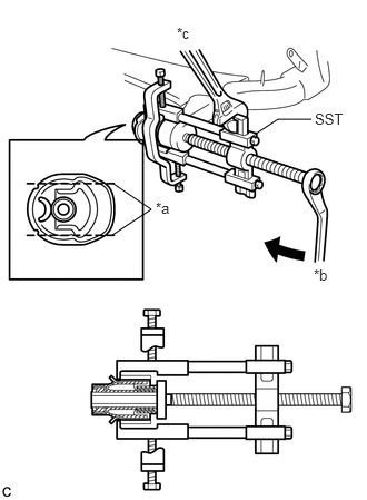
Using SST, remove the rear axle carrier bushing LH from the rear axle beam assembly.
- SST
- 09950-40011
09950-60010 (09951-04020, 09952-04010, 09953-04030, 09954-04020, 09955-04051, 09957-04010, 09958-04011, 09951-00630)
- NOTICE:
-
Apply grease to the threads and tip of the SST center bolt before use.
48725F
18.REMOVE REAR AXLE CARRIER BUSHING RH
- HINT:
-
Perform the same procedure as for the LH side.