INTERIOR PANELS / TRIM FRONT CONSOLE BOX REMOVAL
PROCEDURE

 55405B
1.REMOVE CENTER INSTRUMENT CLUSTER FINISH PANEL SUB-ASSEMBLY
55405B
1.REMOVE CENTER INSTRUMENT CLUSTER FINISH PANEL SUB-ASSEMBLY
58817A
2.REMOVE FRONT NO. 2 CONSOLE BOX INSERT
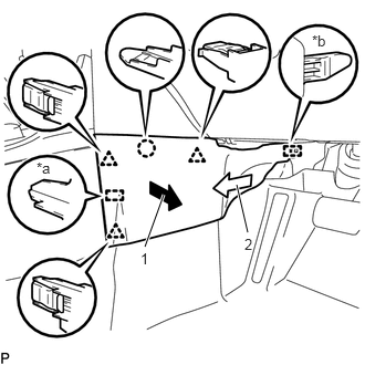
| *a | Guide <A> |
| *b | Guide <B> |
Pull the front No. 2 console box insert in the direction indicated by the arrow (1) to disengage the claw, 3 clips and guide <A>.
Pull the front No. 2 console box insert in the direction indicated by the arrow (2) to disengage the guide <B> to remove the front No. 2 console box insert.
58816B
3.REMOVE CONSOLE BOX INSERT
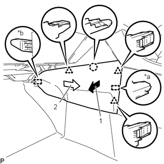
| *a | Guide <A> |
| *b | Guide <B> |
Pull the console box insert in the direction indicated by the arrow (1) to disengage the claw, 3 clips and guide <A>.
Pull the console box insert in the direction indicated by the arrow (2) to disengage the guide <B> to remove the console box insert.
33504F
4.REMOVE SHIFT LEVER KNOB SUB-ASSEMBLY (for Manual Transaxle)
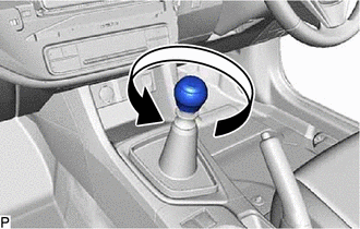
Turn the shift lever knob sub-assembly counterclockwise to remove the shift lever knob sub-assembly.
58843
5.REMOVE SHIFTING HOLE BEZEL (for Manual Transaxle)
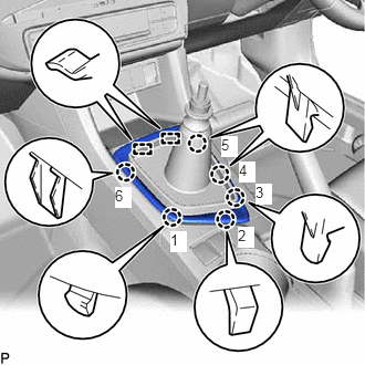
Disengage the 6 claws in the order shown in the illustration.
Disengage the 2 guides to remove the shifting hole bezel.
58843
6.REMOVE SHIFTING HOLE BEZEL (for Automatic Transaxle and CVT)
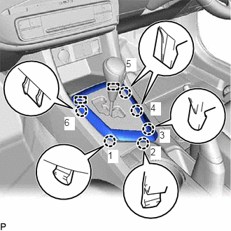
Disengage the 6 claws in the order shown in the illustration.
Disengage the 2 guides to remove the shifting hole bezel.
58804A
7.REMOVE UPPER CONSOLE PANEL SUB-ASSEMBLY
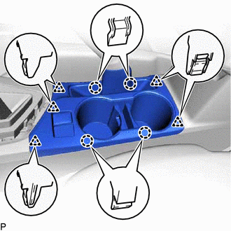
Disengage the 4 claws and 5 clips.
Disconnect each connector to remove the upper console panel sub-assembly.
58821C
8.REMOVE UPPER CONSOLE PANEL
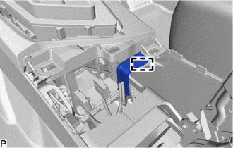
Disengage the clamp.
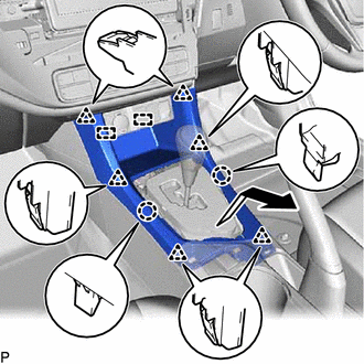
Disengage the 2 claws, 6 clips and 2 guides to remove the upper console panel as shown in the illustration.
58815C
9.REMOVE CONSOLE BOX CARPET
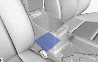
Remove the console box carpet.
58910C
10.REMOVE REAR CONSOLE BOX ASSEMBLY
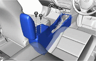
for Manual Transaxle:
Remove the 2 bolts and 2 screws.
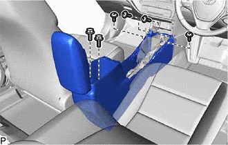
for Automatic Transaxle and CVT:
Remove the 2 bolts and 4 screws.
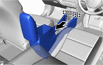
Disengage the 4 guides as shown in the illustration to remove the rear console box assembly.