2NZ-FE ENGINE MECHANICAL CYLINDER HEAD GASKET REMOVAL
PROCEDURE

 1. DISCHARGE FUEL SYSTEM PRESSURE

 27020
2.REMOVE GENERATOR ASSEMBLY

 17111
3.REMOVE INTAKE MANIFOLD

 17141
4.REMOVE EXHAUST MANIFOLD

 5.DISCONNECT WIRE HARNESS
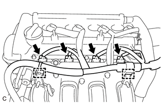
Disconnect the 4 fuel injector assembly connectors.
Disengage the 2 clamps to disconnect the engine wire from the 2 wire harness clamp brackets.
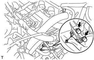
Remove the 2 bolts and disconnect the wire harness.
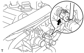
Disconnect the engine coolant temperature sensor connector.
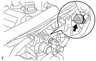
Disconnect the camshaft position sensor connector.

 6.SET NO. 1 CYLINDER TO TDC/COMPRESSION

 15100
7.REMOVE OIL PUMP ASSEMBLY

 23901
8.DISCONNECT FUEL TUBE SUB-ASSEMBLY

 23807
9.REMOVE FUEL DELIVERY PIPE SUB-ASSEMBLY

 23807V
10.REMOVE NO. 1 DELIVERY PIPE SPACER

 23291
11.REMOVE INJECTOR VIBRATION INSULATOR

 23250
12.REMOVE FUEL INJECTOR ASSEMBLY

 44774
13.DISCONNECT UNION TO CONNECTOR TUBE HOSE

 16571C
14.DISCONNECT NO. 1 RADIATOR HOSE

 44774E
15.DISCONNECT VACUUM BRAKE HOSE
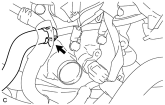
Slide the clip and disconnect the vacuum brake hose from the No. 1 hose to hose tube.

 87245
16.DISCONNECT INLET HEATER WATER HOSE
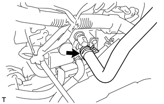
Slide the clip and disconnect inlet heater water hose from the cylinder head sub-assembly.

 87246
17.DISCONNECT OUTLET HEATER WATER HOSE
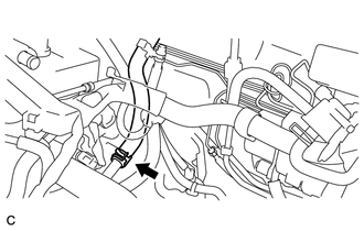
Slide the clip and disconnect the outlet heater water hose from the No. 1 water by-pass pipe.

 16268
18.REMOVE NO. 1 WATER BY-PASS PIPE
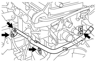
Remove the 2 bolts, 2 nuts and the No. 1 water by-pass pipe.
Remove the gasket from the cylinder block sub-assembly.

 44763A
19.REMOVE NO. 1 HOSE TO HOSE TUBE
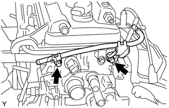
Remove the 2 bolts and No. 1 hose to hose tube.

 13540
20.REMOVE NO. 1 CHAIN TENSIONER ASSEMBLY

 13559
21.REMOVE CHAIN TENSIONER SLIPPER

 13561
22.REMOVE NO. 1 CHAIN VIBRATION DAMPER

 13506
23.REMOVE CHAIN SUB-ASSEMBLY

 13512
24.REMOVE NO. 2 CAMSHAFT

 13511
25.REMOVE CAMSHAFT

 11101
26.REMOVE CYLINDER HEAD SUB-ASSEMBLY
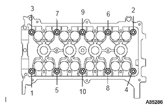
Using an 8 mm bi-hexagon wrench, uniformly loosen and remove the 10 cylinder head set bolts and 10 plate washers in several steps in the order shown in the illustration.
- NOTICE:
- ·
Removing the cylinder head set bolts in the wrong order may cause warpage or cracking of the cylinder head sub-assembly.
·Do not drop the plate washers into the cylinder head sub-assembly.
Using a screwdriver, remove the cylinder head sub-assembly by prying between the cylinder head sub-assembly and cylinder block sub-assembly.
- NOTICE:
-
Be careful not to damage the contact surfaces of the cylinder head sub-assembly and cylinder block sub-assembly.
- HINT:
-
Tape the screwdriver tip before use.

 11115
27.REMOVE CYLINDER HEAD GASKET
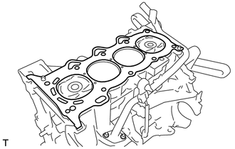
Remove the cylinder head gasket from the cylinder block sub-assembly.