AXLE AND DIFFERENTIAL REAR AXLE HUB ON-VEHICLE INSPECTION
CAUTION / NOTICE / HINT
- HINT:
- ·
Use the same procedure for the RH side and LH side.
·The following procedure is for the LH side.
PROCEDURE

 1.REMOVE REAR WHEEL
58804A
2.REMOVE UPPER CONSOLE PANEL SUB-ASSEMBLY
46441A
3.LOOSEN NO. 2 WIRE ADJUSTING NUT
46430
4.SEPARATE NO. 3 PARKING BRAKE CABLE ASSEMBLY
Click hereBrake>BRAKE (REAR)>REAR BRAKE>REMOVAL
5.SEPARATE REAR DISC BRAKE CALIPER ASSEMBLY
42431
6.REMOVE REAR DISC
Click hereBrake>BRAKE (REAR)>REAR BRAKE>REMOVAL
7.INSPECT REAR AXLE HUB BEARING LOOSENESS
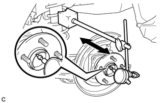
Using a dial indicator, check for looseness near the center of the rear axle hub and bearing assembly.
- Maximum Looseness:
0.05 mm (0.00196 in.)
- NOTICE:
- ·
Ensure that the dial indicator is set perpendicular to the measurement surface.
·Keep the magnet of the dial indicator away from the rear axle hub and bearing assembly.
- HINT:
-
If the looseness exceeds the maximum, replace the rear axle hub and bearing assembly.
8.INSPECT REAR AXLE HUB RUNOUT
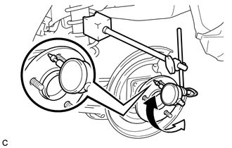
Using a dial indicator, check for runout on the surface of the rear axle hub outside the rear axle hub bolts.
- Maximum Runout:
0.07 mm (0.00275 in.)
- NOTICE:
- ·
Ensure that the dial indicator is set perpendicular to the measurement surface.
·Make sure to set the tip of the dial indicator towards the outside of the rear axle hub bolts.
·Keep the magnet of the dial indicator away from the rear axle hub and bearing assembly.
- HINT:
-
If the runout exceeds the maximum, replace the rear axle hub and bearing assembly.
42431
9.INSTALL REAR DISC
10.INSTALL REAR DISC BRAKE CALIPER ASSEMBLY
46430
11.CONNECT NO. 3 PARKING BRAKE CABLE ASSEMBLY
12.ADJUST PARKING BRAKE
58804A
13.INSTALL UPPER CONSOLE PANEL SUB-ASSEMBLY
14.INSTALL REAR WHEEL