BRAKE (REAR) REAR BRAKE INSTALLATION
CAUTION / NOTICE / HINT
- HINT:
- ·
Use the same procedure for the RH side and LH side.
·The following procedure is for the LH side.
PROCEDURE

 42431
1.INSTALL REAR DISC
42431
1.INSTALL REAR DISC
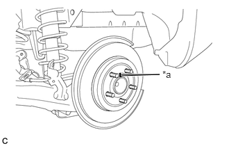
| *a | Matchmark |
Align the matchmarks of the rear disc and rear axle hub and bearing assembly, and install the rear disc.
- NOTICE:
-
When replacing the rear disc with a new one, select the installation position where the rear disc has minimal runout.
2.INSTALL REAR DISC BRAKE CYLINDER MOUNTING
Install the rear disc brake cylinder mounting to the rear axle beam assembly with the 2 bolts.
- Torque:
- 57.4 N*m (585 kgf*cm, 42 ft.*lbf)
3.INSTALL REAR DISC BRAKE BUSHING DUST BOOT
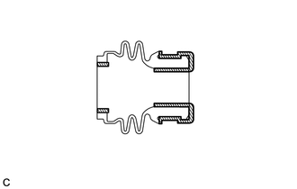

|
Lithium Soap Base Glycol Grease |
Apply a light layer of lithium soap base glycol grease to the entire circumference of 2 new rear disc brake bushing dust boots.
- HINT:
-
Apply more than 0.3 g (0.01 oz) of lithium soap base glycol grease to each rear disc brake bushing dust boot.
Install the 2 rear disc brake bushing dust boots to the rear disc brake cylinder mounting.
4.INSTALL REAR DISC BRAKE CYLINDER SLIDE PIN
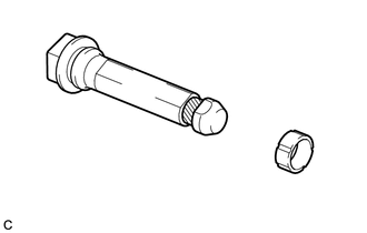
|
|
Lithium Soap Base Glycol Grease |
Apply a light layer of lithium soap base glycol grease to the contact surface of the 2 rear disc brake cylinder slide pins.
Install a new rear disc brake cylinder slide bushing to each rear disc brake cylinder slide pin.
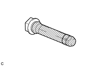
|
|
Lithium Soap Base Glycol Grease |
Apply a light layer of lithium soap base glycol grease to the sliding part and the sealing surfaces of the 2 rear disc brake cylinder slide pins.
Install the 2 rear disc brake cylinder slide pins to rear disc brake cylinder mounting.
Push the 2 rear disc brake cylinder slide pins into the 2 rear disc brake bushing dust boots to engage the pins to the boots.
5.INSTALL REAR DISC BRAKE PAD SUPPORT PLATE
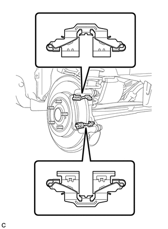
Install the 2 rear disc brake pad support plates to the rear disc brake cylinder mounting.
- NOTICE:
-
Be sure to install each rear disc brake pad support plate in the correct position and direction.
04946
6.INSTALL REAR DISC BRAKE ANTI-SQUEAL SHIM
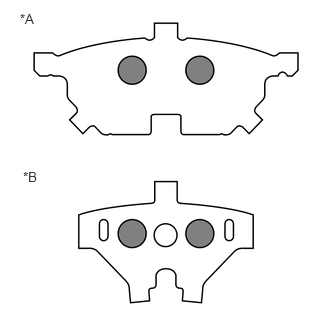
| *A | Outer |
| *B | Inner |

|
Disc Brake Grease |
Apply disc brake grease to the inside of each rear No. 1 disc brake anti-squeal shim as shown in the illustration.
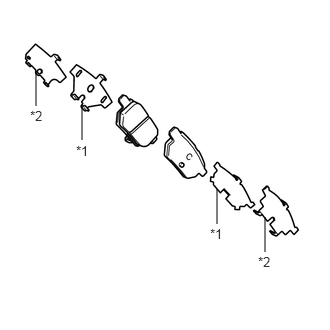
| *1 | Rear No. 1 Disc Brake Anti-squeal Shim |
| *2 | Rear No. 2 Disc Brake Anti-squeal Shim |
Install the rear No. 1 disc brake anti-squeal shim and rear No. 2 disc brake anti-squeal shim to each rear disc brake pad.
- NOTICE:
- ·
When replacing worn pads, the anti-squeal shims must be replaced together with the rear disc brake pads.
·Make sure that disc brake grease is not applied onto the lining surface.
04466
7.INSTALL REAR DISC BRAKE PAD
Install the 2 rear disc brake pads to the rear disc brake cylinder mounting.
- NOTICE:
-
There should be no oil or grease on the friction surfaces of the disc brake pads or the rear disc.
47850
8.INSTALL REAR DISC BRAKE CYLINDER ASSEMBLY
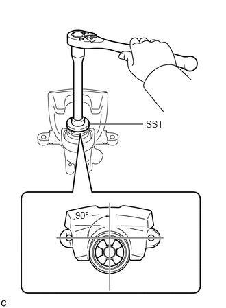
To compensate for pad lining thickness, use SST to adjust the protrusion of the rear disc brake piston by turning it.
- SST
- 09719-12010 (09719-01030)
- NOTICE:
- ·
Place the rear disc between the 2 rear disc brake pads and determine the piston return value.
·Turn the rear disc brake piston to the position where the protrusion on the rear disc brake pad lines up properly with the piston groove.
Hold the 2 rear disc brake cylinder slide pins, and install the rear disc brake cylinder assembly to the rear disc brake cylinder mounting with the 2 bolts.
- Torque:
- 34.3 N*m (350 kgf*cm, 25 ft.*lbf)
47319F
9.CONNECT REAR FLEXIBLE HOSE
Connect the rear flexible hose to the rear disc brake cylinder assembly with a new union bolt and a new gasket.
- Torque:
- 29 N*m (296 kgf*cm, 21 ft.*lbf)
- NOTICE:
-
Install the rear flexible hose lock securely into the lock hole in the rear disc brake cylinder assembly.
46430
10.CONNECT NO. 3 PARKING BRAKE CABLE ASSEMBLY
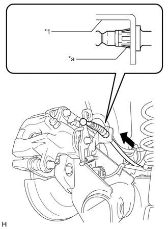
| *1 | Rear Disc Brake Cylinder Assembly |
| *a | Clip |
Engage the clip to install the No. 3 parking brake cable assembly to the rear disc brake cylinder assembly.
- NOTICE:
-
Be sure to engage the clip to the rear disc brake cylinder assembly as shown in the illustration.
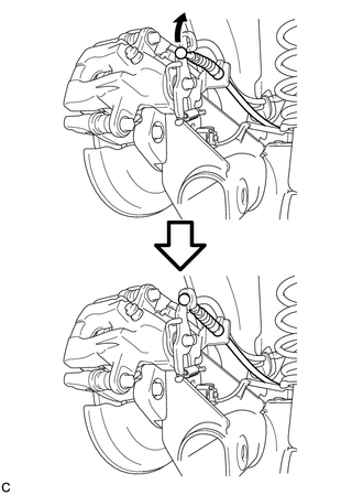
Connect the No. 3 parking brake cable assembly to the rear disc brake cylinder assembly.
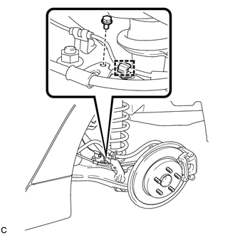
Install the No. 3 parking brake cable assembly to the rear axle beam assembly with the bolt.
- Torque:
- 6.0 N*m (61 kgf*cm, 53 in.*lbf)
Engage the clamp and install the skid control sensor wire LH to the No. 3 parking brake cable assembly.
11. BLEED BRAKE LINE
12.ADJUST PARKING BRAKE
58804A
13.INSTALL UPPER CONSOLE PANEL SUB-ASSEMBLY
14.INSTALL REAR WHEEL