THEFT DETERRENT / KEYLESS ENTRY SMART ENTRY AND START SYSTEM(for Start Function) Power Source Mode does not Change to ON (IG and ACC)
DESCRIPTION
If any of the following operations are performed, the certification ECU (smart key ECU assembly) receives a signal, and changes the power source mode.
With the electrical key transmitter sub-assembly in the cabin, the engine switch is pressed.
When the battery of the electrical key transmitter sub-assembly is depleted, the brake pedal*1 or clutch pedal*2 is depressed and the electrical key transmitter sub-assembly is held near the engine switch.
When the smart key cancel function has been canceled on the customization menu, the brake pedal*1 or clutch pedal*2 is depressed and the electrical key transmitter sub-assembly is held near the engine switch.
*1: except Manual Transaxle
*2: for Manual Transaxle
| Problem Symptom | Data List Item | Active Test Item |
|---|---|---|
| Power source mode does not change to on (IG) or on (ACC) | Power Source Control
·
Start Switch1 ·
Start Switch2 ·
Power Supply Condition ·
IG1 Relay Monitor(Inside) ·
IG2 Relay Monitor(Inside) ·
IG1 Relay Monitor(Outside) ·
IG2 Relay Monitor(Outside) ·
Latch Circuit ·
ACC Relay Monitor |
- |
WIRING DIAGRAM
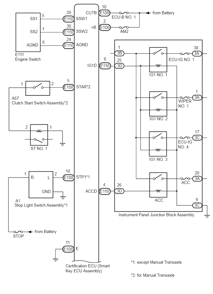
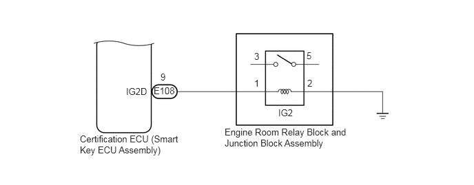
CAUTION / NOTICE / HINT
- NOTICE:
- ·
When using the GTS with the engine switch off, connect the GTS to the DLC3 and turn a courtesy light switch on and off at intervals of 1.5 seconds or less until communication between the GTS and the vehicle begins. Then select Model Code "KEY REGIST" under manual mode and enter the following menus: Body Electrical / Entry&Start(CAN). While using the GTS, periodically turn a courtesy light switch on and off at intervals of 1.5 seconds or less to maintain communication between the GTS and the vehicle.
·The smart entry and start system (for Start Function) uses the LIN communication system and CAN communication system. Inspect the communication function by following How to Proceed with Troubleshooting. Troubleshoot the smart entry and start system (for Start Function) after confirming that the communication systems are functioning properly.
·Make sure that no DTCs are output. If any DTCs are output, proceed to the Diagnostic Trouble Code Chart.
·If the smart entry and start system is disabled through the customize function, enable the system before performing troubleshooting.
·Before replacing the certification ECU (smart key ECU assembly) electrical key transmitter sub-assembly, refer to smart entry and start system (for Start Function) Precaution.
·Inspect the fuses of circuits related to this system before performing the following procedure.
·After completing repairs, confirm that the problem does not occur.
- HINT:
-
When the cable is disconnected and reconnected to the negative (-) battery terminal, the power source mode returns to the state it was in before the cable was disconnected.
PROCEDURE
Check the wireless door lock function by operating the electrical key transmitter sub-assembly.
- OK:
Wireless door lock function operates.
- Result:
Proceed to OK NG
OK
NG
- Result:
Proceed to OK NG
OK
NG
- Result:
Proceed to OK NG
OK
NG
Remove the battery from the electrical key transmitter sub-assembly.
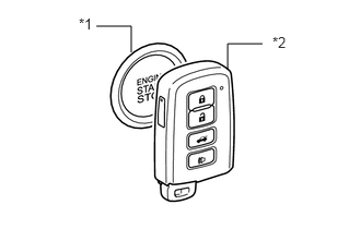
| *1 | Engine Switch |
| *2 | Electrical Key Transmitter Sub-assembly |
With the brake pedal*1 or clutch pedal*2 depressed, hold the electrical key transmitter sub-assembly near the engine switch and check if the power source mode changes.
*1: except Manual Transaxle
*2: for Manual Transaxle
- HINT:
-
If the power source mode changes, the cabin verification is malfunctioning.
- OK:
The power source mode changes.
- Result:
Proceed to OK NG
OK
NG
Connect the GTS to the DLC3.
Turn the engine switch on (IG).
Turn the GTS on.
Enter the following menus: Body Electrical / Power Source Control / Data List.
Read the Data List according to the display on the GTS.
- Body Electrical > Power Source Control > Data List
-
Tester Display Measurement Item Range Normal Condition Diagnostic Note Start Switch1 Engine switch 1 status ON or OFF ON: Engine switch pressed
OFF: Engine switch not pressed·If the engine switch is pressed for a short time, the display may not change.
·Use this item to determine whether the engine switch input signal is malfunctioning.
Start Switch2 Engine switch 2 status ON or OFF ON: Engine switch pressed
OFF: Engine switch not pressed·Backup for engine switch 1. However, when the engine switch is pressed and held, the control functions only when both engine switch 1 and 2 are normal.
·Behaves the same way as engine switch 1.
- Body Electrical > Power Source Control > Data List
-
Tester Display Start Switch1 Start Switch2 - 50003 223 4,5
- OK:
The GTS display changes correctly in response to the operation of the engine switch.
- Result:
Proceed to OK NG
OK
NG
Remove the engine switch.
Click hereEngine / Hybrid System>2ZR-FE STARTING>ENGINE SWITCH>REMOVAL
Inspect the engine switch.
Click hereEngine / Hybrid System>2ZR-FE STARTING>ENGINE SWITCH>INSPECTION
- Result:
Proceed to OK NG
OK
NG
Disconnect the E110 certification ECU (smart key ECU assembly) connector.
Measure the resistance according to the value(s) in the table below.
- Standard Resistance:
Tester Connection Condition Specified Condition E110-28 (SSW1) - E111-5 (SS1) Always Below 1 Ω E110-30 (SSW2) - E111-1 (SS2) Always Below 1 Ω E110-28 (SSW1) or E111-5 (SS1) - Body ground Always 10 kΩ or higher E110-30 (SSW2) or E111-1 (SS2) - Body ground Always 10 kΩ or higher
- Result:
Proceed to OK NG
OK
NG
Connect the GTS to the DLC3.
Turn the engine switch on (IG).
Turn the GTS on.
Enter the following menus: Body Electrical / Power Source Control / Data List.
Read the Data List according to the display on the GTS.
except Manual Transaxle:
- Body Electrical > Power Source Control > Data List
-
Tester Display Measurement Item Range Normal Condition Diagnostic Note Stop Light Switch1 State of brake pedal ON or OFF ON: Brake pedal depressed
OFF: Brake pedal released·Use this item to determine whether the stop light switch is malfunctioning.
·The engine cannot be started when this item is OFF.
·When this item is malfunctioning, the engine can be started by pressing and holding the engine switch for a certain period of time.
- Body Electrical > Power Source Control > Data List
-
Tester Display Stop Light Switch1 - 50003 223 3
for Manual Transaxle:
- Body Electrical > Power Source Control > Data List
-
Tester Display Measurement Item Range Normal Condition Diagnostic Note Neutral SW/ Clutch SW State of clutch pedal ON or OFF ON: Clutch pedal depressed
OFF: Clutch pedal released·Use this item to help determine if the clutch start switch assembly is malfunctioning.
·The engine cannot be started when this item is OFF.
- Body Electrical > Power Source Control > Data List
-
Tester Display Neutral SW/ Clutch SW - 50003 223 6
- OK:
ON (brake pedal is depressed) and OFF (brake pedal is released) appear on the screen. (except Manual Transaxle)
ON (clutch pedal is depressed) and OFF (clutch pedal is released) appear on the screen. (for Manual Transaxle)
- Result:
Result Proceed to OK A NG (except Manual Transaxle) B NG (for Manual Transaxle) C
A
B
C
Connect the GTS to the DLC3.
Turn the engine switch on (IG).
Turn the GTS on.
Enter the following menus: Body Electrical / Power Source Control / Data List.
Read the Data List according to the display on the GTS.
- Body Electrical > Power Source Control > Data List
-
Tester Display Measurement Item Range Normal Condition Diagnostic Note Power Supply Condition Power supply state All OFF, ACC ON, IG1 ON, IG2 ON or ST ON ALL OFF: Engine switch off (ACC and IG)
ACC ON: Engine switch on (ACC)
IG1 ON: Engine switch on (IG) (IG1 relay on)
IG2 ON: Engine switch on (IG) (IG2 relay on)
ST ON: Sending engine start request signalSince the IG1 and IG2 relays turn on at approximately the same time, IG1 ON may not be displayed (the IG1 relay turns on for a very short time).
- Body Electrical > Power Source Control > Data List
-
Tester Display Power Supply Condition - 50003 223 18
With the engine switch off and brake pedal depressed, hold the electrical key transmitter sub-assembly near the engine switch for 2 seconds or more and read the Data List.
- HINT:
-
If the smart key function has been canceled on the customization menu, ACC ON is displayed in the Data List.
- OK:
IG2 ON is displayed in the Data List.
- Result:
Proceed to OK NG
OK
NG
Read the Data List according to the display on the GTS.
- Body Electrical > Power Source Control > Data List
-
Tester Display Measurement Item Range Normal Condition Diagnostic Note Power Supply Condition Power supply state All OFF, ACC ON, IG1 ON, IG2 ON or ST ON All OFF: Engine switch off (ACC and IG)
ACC ON: Engine switch on (ACC)
IG1 ON: Engine switch on (IG) (IG1 relay on)
IG2 ON: Engine switch on (IG) (IG2 relay on)
ST ON: Sending engine start request signalSince the IG1 and IG2 relays turn on at approximately the same time, IG1 ON may not be displayed (the IG1 relay turns on for a very short time).
- Body Electrical > Power Source Control > Data List
-
Tester Display Power Supply Condition - 50003 223 18
Measure the voltage while checking the Data List on the GTS.
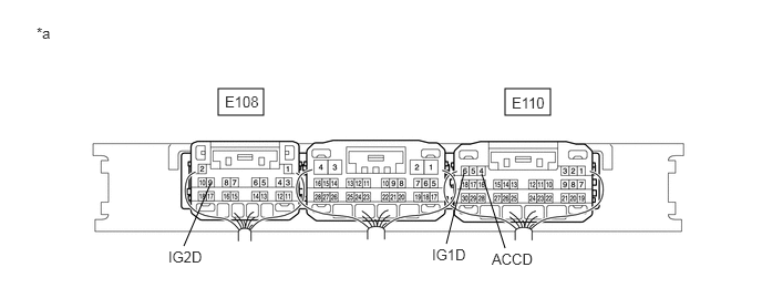
| *a | Component with harness connected
(Certification ECU (Smart Key ECU Assembly)) |
- | - |
- Standard Voltage:
Tester Connection Condition Specified Condition E110-6 (IG1D) - Body ground Engine switch off 1 V or less Engine switch on (ACC) 1 V or less Engine switch on (IG) 9 V or higher E108-9 (IG2D) - Body ground Engine switch off 1 V or less Engine switch on (ACC) 1 V or less Engine switch on (IG) 9 V or higher E110-4 (ACCD) - Body ground Engine switch off 1 V or less Engine switch on (IG) 8.5 V or higher Engine switch on (ACC) 8.5 V or higher
- Result:
Proceed to OK NG
OK
Click hereGeneral>INTRODUCTION>HOW TO TROUBLESHOOT ECU CONTROLLED SYSTEMS>HOW TO PROCEED WITH TROUBLESHOOTING
NG
Check for DTCs.
- Body Electrical > Entry&Start > Trouble Codes
- 50001 125
- Result:
Result Proceed to The following DTCs are not output:
·B2784
·B278A
A DTC B2784 is output. B DTC B278A is output. C
A
B
C
Click hereVehicle Exterior>LIGHTING (EXT)>STOP LIGHT SWITCH>ON-VEHICLE INSPECTION
- Result:
Proceed to OK NG
OK
NG
- Result:
Proceed to OK NG
OK
NG
Click hereEngine / Hybrid System>2ZR-FE STARTING>RELAY>ON-VEHICLE INSPECTION
- Result:
Proceed to OK NG
OK
NG
OK
NG
Disconnect the E108 certification ECU (smart key ECU assembly) connector.
Disconnect the A57 clutch start switch assembly connector.
Measure the resistance according to the value(s) in the table below.
- Standard Resistance:
Tester Connection Condition Specified Condition E108-5 (STAR) - A57-2 Always Below 1 Ω E108-5 (STAR) or A57-2 - Body ground Always 10 kΩ or higher
- Result:
Proceed to OK NG
OK
NG
Disconnect the A57 clutch start switch assembly connector.
Remove the ST NO. 1 relay from the engine room relay block and junction block assembly.
Measure the resistance according to the value(s) in the table below.
- Standard Resistance:
Tester Connection Condition Specified Condition A57-1 - ST NO. 1 relay terminal 2 Always Below 1 Ω ST NO. 1 relay terminal 1 - Body ground Always Below 1 Ω A57-1 or ST NO. 1 relay terminal 2 - Body ground Always 10 kΩ or higher
- Result:
Proceed to OK NG
OK
NG