LIGHTING (EXT) STOP LIGHT SWITCH ON-VEHICLE INSPECTION
PROCEDURE

 84340
1.INSPECT STOP LIGHT SWITCH ASSEMBLY
a.

1.448,0.125 1.917,0.406
0.469,0.281
1.344,1.229 1.083,1.604
false
1.719,1.229 1.958,1.604
false
0.167,0.063 0.375,0.26
0.208,0.198
10
false
*a
1.875,1.615 2.313,1.833
0.438,0.219
10
false
GND
1,1.615 1.188,1.833
0.188,0.219
10
false
B
1.594,0.188 1.865,0.354
0.271,0.167
10
false
A1
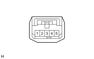
| *a | Front view of wire harness connector
(to Stop Light Switch Assembly) |
Disconnect the A1 stop light switch assembly connector.
b.
Measure the voltage and resistance on the wire harness side connector according to the value(s) in the table below.
- Standard Voltage:
Tester Connection Condition Specified Condition A1-1 (B) - A1-3 (GND) Always 11 to 14 V
- Standard Resistance:
Tester Connection Condition Specified Condition A1-3 (GND) - Body ground Always Below 1 Ω
If the result is not as specified, repair or replace the wire harness or connector.
c.

1.5,0.229 1.958,0.51
0.458,0.281
1.708,1.281 1.177,1.719
false
1.927,1.281 2.427,1.719
false
0.198,0.094 0.427,0.271
0.229,0.177
10
false
*a
1.646,0.281 1.906,0.458
0.26,0.177
10
false
A1
0.948,1.74 1.271,1.917
0.323,0.177
10
false
GND
2.344,1.74 2.667,1.917
0.323,0.177
10
false
OUT
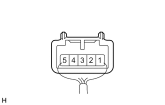
| *a | Component with harness connected
(Stop Light Switch Assembly) |
Reconnect the A1 stop light switch assembly connector.
d.
Measure the voltage according to the value(s) in the table below.
- Standard Voltage:
Tester Connection Condition Specified Condition A1-2 (OUT) - A1-3 (GND) Ignition switch off, brake pedal not depressed Below 1 V A1-2 (OUT) - A1-3 (GND) Ignition switch off, brake pedal depressed 11 to 14 V
If the result is not as specified, replace the stop light switch assembly.