1ZR-FE ENGINE MECHANICAL ENGINE ASSEMBLY REMOVAL
CAUTION / NOTICE / HINT
- CAUTION:
-
The engine assembly with transaxle is very heavy. Be sure to follow the procedure described in the repair manual, or the engine lifter may suddenly drop.
PROCEDURE

 1. PRECAUTION
- NOTICE:
-
After turning the ignition switch off, waiting time may be required before disconnecting the cable from the negative (-) battery terminal. Therefore, make sure to read the disconnecting the cable from the negative (-) battery terminal notices before proceeding with work.
-
Click hereGeneral>INTRODUCTION>REPAIR INSTRUCTION>PRECAUTION
2. DISCHARGE FUEL SYSTEM PRESSURE
3.ALIGN FRONT WHEELS FACING STRAIGHT AHEAD
4. SECURE STEERING WHEEL
5.DISCONNECT CABLE FROM NEGATIVE BATTERY TERMINAL
- NOTICE:
-
When disconnecting the cable, some systems need to be initialized after the cable is reconnected.
-
Click hereGeneral>INTRODUCTION>REPAIR INSTRUCTION>INITIALIZATION
6.REMOVE FRONT WHEELS
51442C
7.REMOVE ENGINE UNDER COVER LH
Remove the 2 bolts, 4 screws, 3 clips and engine under cover LH.
51441C
8.REMOVE ENGINE UNDER COVER RH
Remove the 3 bolts, 4 screws, 3 clips and engine under cover RH.
9.DRAIN ENGINE COOLANT
10.DRAIN ENGINE OIL
11.DRAIN AUTOMATIC TRANSAXLE FLUID
11212
12.REMOVE NO. 2 CYLINDER HEAD COVER
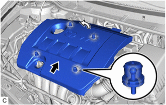

|
Disengage the 2 rear clips first |

|
Disengage the 2 front clips next |
Lift the rear of the No. 2 cylinder head cover to disengage the 2 rear clips. Lift the front of the No. 2 cylinder head cover to disengage the 2 front clips and remove the No. 2 cylinder head cover.
- NOTICE:
-
Attempting to disengage both front and rear clips at the same time may cause the No. 2 cylinder head cover to break.
17705
13.REMOVE AIR CLEANER CAP WITH AIR CLEANER HOSE
17701
14.REMOVE AIR CLEANER CASE SUB-ASSEMBLY
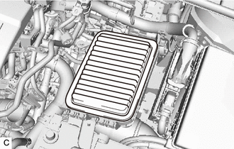
Remove the air cleaner filter element sub-assembly from the air cleaner case sub-assembly.
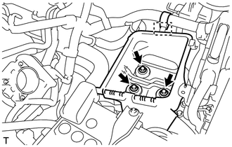
Disconnect the wire harness clamp from the air cleaner case sub-assembly.
Remove the 3 bolts and air cleaner case sub-assembly.
15.REMOVE BATTERY
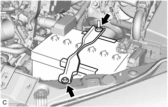
Loosen the nut, and disconnect the cable from the positive (+) battery terminal.
Remove the bolt, nut and battery clamp sub-assembly.
Remove the battery and battery tray from the battery carrier.
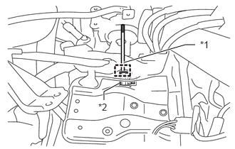
| *1 | Battery Clamp Bolt |
| *2 | Battery Carrier Support |
Remove the battery clamp bolt from the battery carrier support.
74411
16.REMOVE BATTERY CARRIER
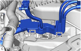
Disconnect the 2 wire harness clamps from the battery carrier.
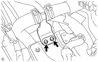
Remove the 2 bolts and disconnect the radiator pipe from the battery carrier.
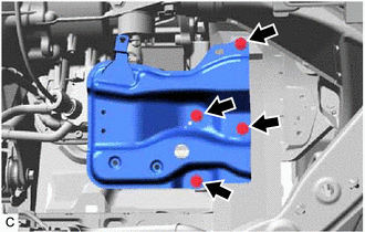
Remove the 4 bolts and battery carrier.
16571C
17.DISCONNECT NO. 1 RADIATOR HOSE
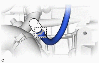
Disconnect the breather plug hose from the clamp.
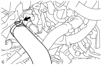
Slide the clip and disconnect the No. 1 radiator hose from the cylinder head sub-assembly.
16572D
18.DISCONNECT NO. 2 RADIATOR HOSE
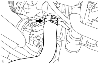
Slide the clip and disconnect the No. 2 radiator hose from the water inlet.
33820B
19.SEPARATE TRANSMISSION CONTROL CABLE ASSEMBLY
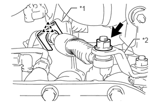
| *1 | No. 1 Transmission Control Cable Bracket |
| *2 | Control Shaft Lever |
Remove the nut and separate the transmission control cable assembly from the control shaft lever.
Remove the clip and separate the transmission control cable assembly from the No. 1 transmission control cable bracket.
20.DISCONNECT OIL COOLER HOSE
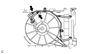
Slide the 2 clips and disconnect the 2 oil cooler hoses from the oil cooler tube.
23826
21.DISCONNECT NO. 1 FUEL VAPOR FEED HOSE
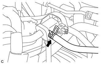
Slide the clip and disconnect the No. 1 fuel vapor feed hose from the purge valve (purge VSV).
44774
22.DISCONNECT UNION TO CONNECTOR TUBE HOSE
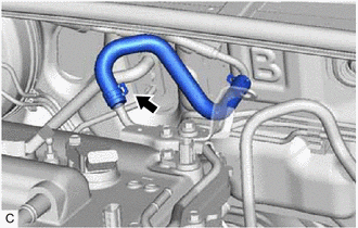
Slide the clip and disconnect the union to connector tube hose from the air tube.
87246
23.DISCONNECT HEATER WATER OUTLET HOSE
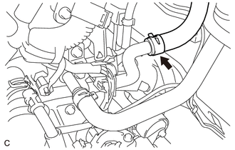
Slide the clip and disconnect the heater water outlet hose from the No. 1 water by-pass pipe.
87245
24.DISCONNECT HEATER WATER INLET HOSE
23901
25.DISCONNECT FUEL TUBE SUB-ASSEMBLY
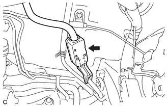
Disengage the claw and remove the No. 1 fuel pipe clamp.
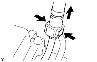
Pinch the retainer as shown in the illustration, then pull the fuel tube connector off of the fuel pipe.
- NOTICE:
- ·
Remove any dirt and foreign matter from the fuel tube connector before performing this work.
·Do not allow any scratches or foreign matter to get on the parts when disconnecting them, as the fuel tube connector has O-rings that seal the fuel pipe.
·Perform this work by hand. Do not use any tools.
·Do not forcibly bend, kink or twist the nylon tube.
·Protect the disconnected part by covering it with a plastic bag after disconnecting the fuel tube sub-assembly.
·If the fuel tube connector and fuel pipe are stuck, push and pull to release them.
16361A
26.REMOVE V-RIBBED BELT
27020
27.REMOVE GENERATOR ASSEMBLY
88310
28.SEPARATE COMPRESSOR ASSEMBLY WITH PULLEY
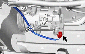
Disconnect the connector.
Disengage the clamp.
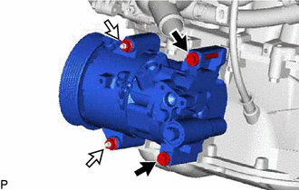
|
|
Bolt |
|
|
Nut |
Remove the 2 bolts and 2 nuts.
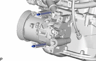
Using an E8 "TORX" socket wrench, remove the 2 stud bolts.
- HINT:
-
Secure the compressor and hoses off to the side instead of discharging the A/C system.
Separate the compressor assembly with pulley from the engine assembly.
29.DISCONNECT WIRE HARNESS

Pull up the lever and disconnect the ECM connector.
Disconnect the wire harness clamp.
Remove the No. 1 engine room relay block cover from the engine room relay block and junction block assembly.
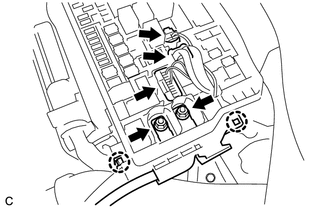
Remove the 2 nuts from the engine room relay block and junction block assembly.
Disconnect the 3 wire harness connectors.
Disengage the 2 claws and disconnect the wire harness from the engine room relay block and junction block assembly.
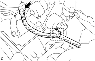
Remove the bolt and disconnect the clamp and No. 3 engine wire from the automatic transaxle assembly.
Disconnect all the wire harnesses and connectors.
- HINT:
-
Make sure that no wire harness is connected between the vehicle body and engine assembly.
45259A
30.REMOVE COLUMN HOLE COVER SILENCER SHEET
45260
31.SEPARATE NO. 2 STEERING INTERMEDIATE SHAFT ASSEMBLY
45025D
32.SEPARATE NO. 1 STEERING COLUMN HOLE COVER SUB-ASSEMBLY
17410
33.REMOVE FRONT EXHAUST PIPE ASSEMBLY (TWC: Front and Rear Catalyst)
34.REMOVE DRIVE SHAFT ASSEMBLY
11361J
35.REMOVE FLYWHEEL HOUSING UNDER COVER
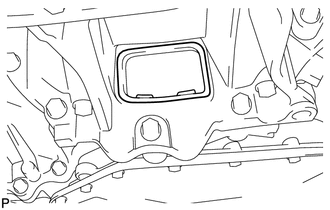
Remove the flywheel housing under cover from the stiffening crankcase assembly.
32101A
36.REMOVE DRIVE PLATE AND TORQUE CONVERTER ASSEMBLY SETTING BOLT
51201
37.REMOVE FRONT SUSPENSION CROSSMEMBER SUB-ASSEMBLY
38.REMOVE ENGINE ASSEMBLY WITH TRANSAXLE
Set an engine lifter.
- NOTICE:
- ·
Using height adjustment attachments and plate lift attachments, place the engine assembly with transaxle horizontally.
·Do not perform any procedure while the engine assembly with transaxle is suspended because doing so may cause the engine assembly with transaxle to drop, resulting in injury. However, the engine assembly with transaxle needs to be suspended when it is installed to or removed from an engine stand.
Remove the center engine mounting member sub-assembly.
Click hereSuspension>FRONT SUSPENSION>FRONT SUSPENSION MEMBER>REMOVAL
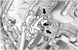
Remove the bolt and 2 nuts, and separate the engine mounting insulator sub-assembly RH.
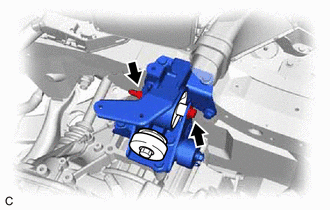
Remove the through bolt and nut, and separate the engine mounting insulator LH.
- HINT:
-
When removing the through bolt, keep the nut from rotating.
Carefully remove the engine assembly with transaxle from the vehicle.
- NOTICE:
-
Make sure that the engine assembly with transaxle is clear of all wiring and hoses.
12361A
39.REMOVE FRONT ENGINE MOUNTING INSULATOR
- HINT:
-
Perform this procedure only when replacement of the front engine mounting insulator is necessary.
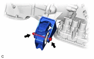
Remove the through bolt, nut and front engine mounting insulator from the front engine mounting bracket.
- HINT:
-
Because the nut has its own stopper, do not turn the nut. Loosen the through bolt with the nut secured.
12371A
40.REMOVE REAR ENGINE MOUNTING INSULATOR
- HINT:
-
Perform this procedure only when replacement of the rear engine mounting insulator is necessary.
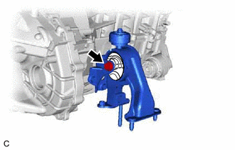
Remove the through bolt and rear engine mounting insulator from the rear engine mounting bracket.
12372A
41.REMOVE ENGINE MOUNTING INSULATOR LH
- HINT:
-
Perform this procedure only when replacement of the engine mounting insulator LH is necessary.
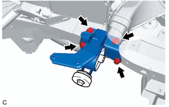
Remove the 4 bolts and engine mounting insulator LH.
12305
42.REMOVE ENGINE MOUNTING INSULATOR SUB-ASSEMBLY RH
- HINT:
-
Perform this procedure only when replacement of the engine mounting insulator sub-assembly RH is necessary.
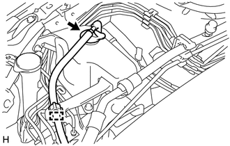
Disengage the clamp to separate the reserve hose.
Remove the reserve tank cap sub-assembly.
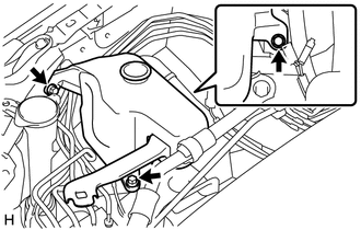
Remove the 3 bolts and radiator reserve tank assembly.
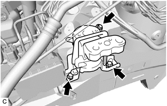
Remove the 3 bolts and engine mounting insulator sub-assembly RH.
43.REMOVE WIRE HARNESS CLAMP BRACKET
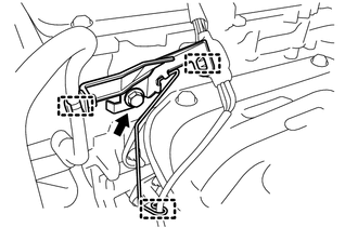
Disengage the 3 clamps and remove the bolt and wire harness clamp bracket.
44.INSTALL ENGINE HANGER
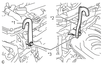
| *1 | No. 1 Engine Hanger (Part No.12281-37021) |
| *2 | No. 2 Engine Hanger (Part No.12282-37011) |
| *3 | Bolt (Part No. 91552-81050) |
Install the No. 1 engine hanger and No. 2 engine hanger with the 2 bolts.
- Torque:
- 43 N*m (438 kgf*cm, 32 ft.*lbf)
Attach an engine sling device and hang the engine assembly with a chain block.
- NOTICE:
- ·
Pay attention to the angle of the sling device as the engine assembly or No. 1 engine hanger and No. 2 engine hanger may be damaged or deformed if the angle is incorrect.
·Do not perform any procedure while the engine assembly with is suspended because doing so may cause the engine assembly with transaxle to drop, resulting in injury. However, the engine assembly with transaxle needs to be suspended when it is installed to or removed from an engine stand.
11363A
45.REMOVE FLYWHEEL HOUSING SIDE COVER
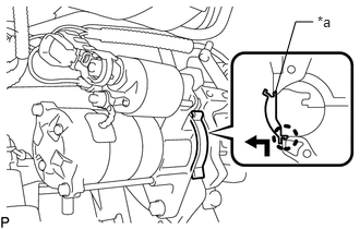
| *a | Protruding Portion |
Push up the flywheel housing side cover as shown in the illustration to disengage the claw, and remove the flywheel housing side cover.
28100
46.REMOVE STARTER ASSEMBLY
82121
47.REMOVE ENGINE WIRE
Remove the engine wire from the engine assembly with transaxle.
30500
48.REMOVE AUTOMATIC TRANSAXLE ASSEMBLY
32101
49.REMOVE DRIVE PLATE AND RING GEAR SUB-ASSEMBLY
50.INSTALL ENGINE TO ENGINE STAND
Install the engine assembly to an engine stand.
- NOTICE:
- ·
Adjust the angle of the sling device carefully to prevent the engine assembly or engine hangers from deforming or becoming damaged.
·Servicing an engine assembly while it is hanging is dangerous. This can be done only when installing/removing the engine assembly to/from an engine stand.
51.REMOVE ENGINE HANGER
Remove the 2 bolts, No. 1 engine hanger and No. 2 engine hanger.