FRONT SUSPENSION FRONT SUSPENSION MEMBER REMOVAL
PROCEDURE

 1.ALIGN FRONT WHEELS FACING STRAIGHT AHEAD

 2. SECURE STEERING WHEEL

 45259A
3.REMOVE COLUMN HOLE COVER SILENCER SHEET

 45260
4.SEPARATE NO. 2 STEERING INTERMEDIATE SHAFT ASSEMBLY

 45025D
5.SEPARATE NO. 1 STEERING COLUMN HOLE COVER SUB-ASSEMBLY

 6.REMOVE FRONT WHEELS

 51442C
7.REMOVE ENGINE UNDER COVER LH

 51441C
8.REMOVE ENGINE UNDER COVER RH

 45047
9.SEPARATE TIE ROD END SUB-ASSEMBLY LH

 45046
10.SEPARATE TIE ROD END SUB-ASSEMBLY RH
- HINT:
-
Perform the same procedure as for the LH side.

 48810
11.SEPARATE FRONT STABILIZER LINK ASSEMBLY LH

 48820B
12.SEPARATE FRONT STABILIZER LINK ASSEMBLY RH
- HINT:
-
Perform the same procedure as for the LH side.

 48069
13.SEPARATE FRONT LOWER NO. 1 SUSPENSION ARM SUB-ASSEMBLY LH

 48068
14.SEPARATE FRONT LOWER NO. 1 SUSPENSION ARM SUB-ASSEMBLY RH
- HINT:
-
Perform the same procedure as for the LH side.

 51201
15.REMOVE FRONT SUSPENSION CROSSMEMBER SUB-ASSEMBLY
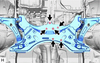
Remove the 3 bolts and 3 nuts.
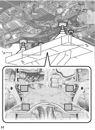
| *a | Engine Lifter |
| *b | Attachment |

|
Attachment Placement Location |
Support the front suspension crossmember sub-assembly with an engine lifter using 4 attachments or equivalent tools as shown in the illustration.
- CAUTION:
- ·
The front suspension crossmember sub-assembly is a heavy component. Make sure that it is supported securely.
·Make sure to secure the front suspension crossmember sub-assembly to prevent it from dropping.
- NOTICE:
-
Use the attachments to keep the front suspension crossmember sub-assembly level.
Remove the 4 bolts and front suspension crossmember sub-assembly.
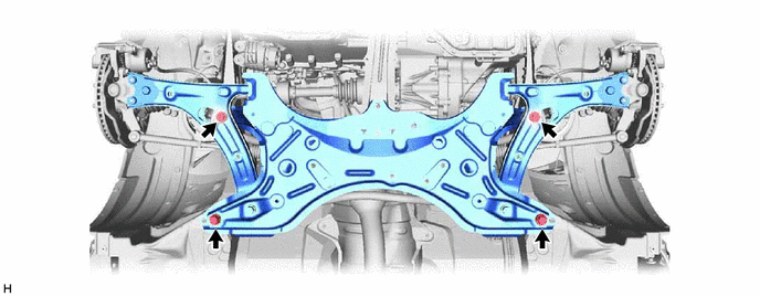
Slowly lower the front suspension crossmember sub-assembly.
- NOTICE:
-
When lowering the front suspension crossmember sub-assembly, be careful not to damage the vehicle body or other components installed on the vehicle.

 51963B
16.REMOVE FRONT TRANSPORT HOOK
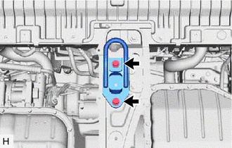
Remove the 2 bolts and front transport hook from the center engine mounting member sub-assembly.

 51204A
17.REMOVE CENTER ENGINE MOUNTING MEMBER SUB-ASSEMBLY
for Manual Transaxle:
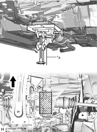
| *a | Jack |
| *b | Wooden Block |

|
Front of the Vehicle |

|
Wooden Block Placement Location |
Using a jack and wooden block, support the engine and transaxle assembly.
for Automatic Transaxle and CVT:
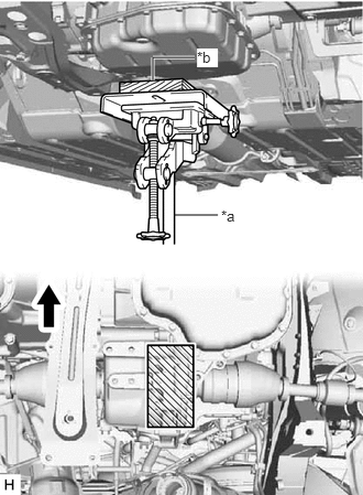
| *a | Jack |
| *b | Wooden Block |

|
Front of the Vehicle |

|
Wooden Block Placement Location |
Using a jack and wooden block, support the engine and transaxle assembly.
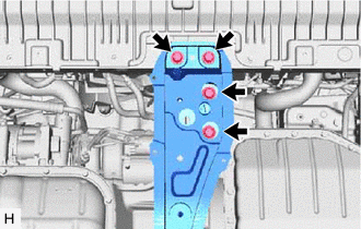
Remove the 4 bolts and center engine mounting member sub-assembly.

 48811
18.REMOVE FRONT STABILIZER BAR

 19.REMOVE STEERING LINK ASSEMBLY

 48069
20.REMOVE FRONT LOWER NO. 1 SUSPENSION ARM SUB-ASSEMBLY LH

 48068
21.REMOVE FRONT LOWER NO. 1 SUSPENSION ARM SUB-ASSEMBLY RH
- HINT:
-
Perform the same procedure as for the LH side.