INTERIOR PANELS / TRIM LOWER INSTRUMENT PANEL REMOVAL
PROCEDURE

 1. PRECAUTION
2.REMOVE UPPER INSTRUMENT PANEL ASSEMBLY
3.REMOVE CONSOLE BOX ASSEMBLY
67913
4.REMOVE FRONT DOOR SCUFF PLATE RH
62111C
5.REMOVE COWL SIDE TRIM BOARD RH
55545
6.REMOVE FUSE BOX OPENING COVER
w/o Smart Entry and Start System:
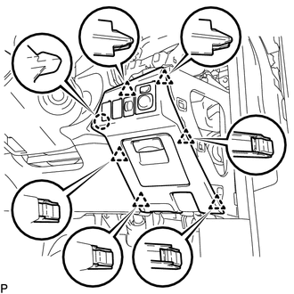
Disengage the claw and 6 clips.
Disconnect each connector to remove the fuse box opening cover.
w/ Smart Entry and Start System:
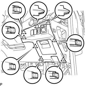
Disengage the 8 clips.
Disconnect each connector to remove the fuse box opening cover.
55446A
7.REMOVE NO. 1 SWITCH HOLE BASE
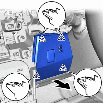
Disengage the 4 clips.
Disconnect the connector to remove the No. 1 switch hole base as shown in the illustration.
55447C
8.REMOVE NO. 2 SWITCH HOLE BASE
w/o Smart Entry and Start System:
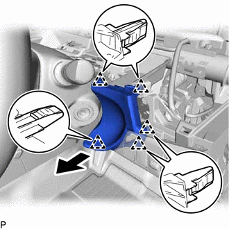
Disengage the 5 clips to remove the No. 2 switch hole base as shown in the illustration.
w/ Smart Entry and Start System:
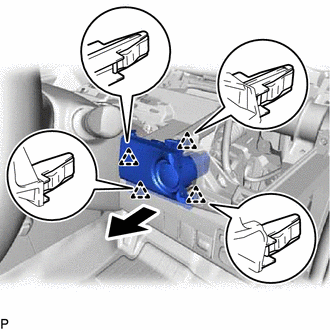
Disengage the 4 clips as shown in the illustration.
Disconnect the connector to remove the No. 2 switch hole base.
55606
9.REMOVE NO. 1 INSTRUMENT PANEL UNDER COVER SUB-ASSEMBLY
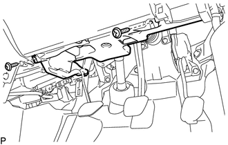
Remove the 2 screws <G>.
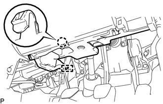
Disengage the claw and guide, to remove the No. 1 instrument panel under cover sub-assembly.
55045
10.REMOVE LOWER INSTRUMENT PANEL FINISH PANEL SUB-ASSEMBLY
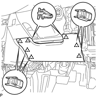
Disengage the 7 clips to remove the lower instrument panel finish panel sub-assembly.
86211
11.REMOVE NO. 1 RADIO BRACKET
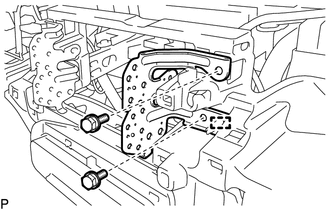
Remove the 2 bolts <C>.
Disengage the guide to remove the No. 1 radio bracket.
86212
12.REMOVE NO. 2 RADIO BRACKET
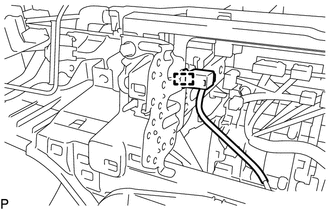
Disengage the clamp.
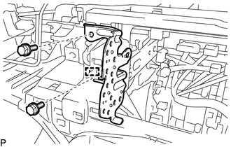
Remove the 2 bolts <C>.
Disengage the guide to remove the No. 2 radio bracket.
13.REMOVE AIR CONDITIONING PANEL ASSEMBLY (for Manual Air Conditioning System)
14.REMOVE CENTER INSTRUMENT PANEL SAFETY PAD RETAINER WITH AIR CONDITIONING CONTROL ASSEMBLY (for Automatic Air Conditioning System)
55434B
15.REMOVE LOWER CENTER INSTRUMENT PANEL FINISH PANEL
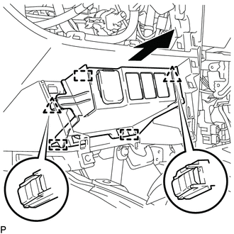
Disengage the 2 clips and 3 guides as shown in the illustration.
Disengage the clamp.
Disconnect each connector to remove the lower center instrument panel finish panel.
67914
16.REMOVE FRONT DOOR SCUFF PLATE LH
- HINT:
-
Use the same procedure as for the RH side.
62112
17.REMOVE COWL SIDE TRIM BOARD LH
- HINT:
-
Use the same procedure as for the RH side.
55550
18.REMOVE GLOVE COMPARTMENT DOOR ASSEMBLY
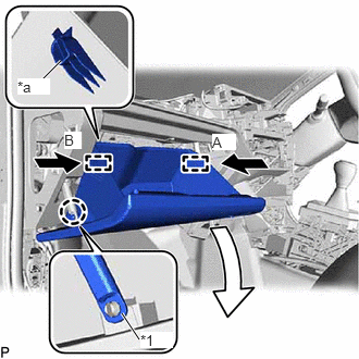
| *1 | Glove Compartment Door Stopper Sub-assembly |
| *a | Stopper |
Disengage the claw to disconnect the glove compartment door stopper sub-assembly.
Slightly bend the stoppers (A) and (B) in the directions indicated by the arrows in the illustration and open the glove compartment door assembly until the stoppers are disengaged.
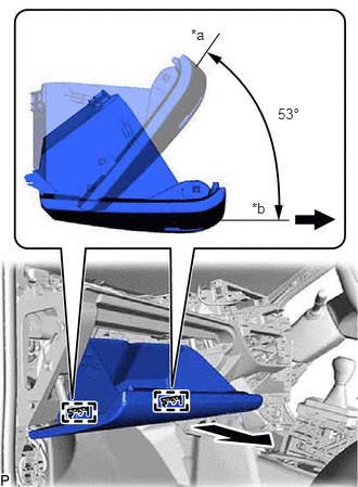
| *a | Closed |
| *b | Open Approximately 53° |
Open the glove compartment door assembly to approximately 53° from its closed position. Pull it horizontally in the direction indicated by the arrow to disengage the 2 hinges and remove the glove compartment door assembly.
- NOTICE:
-
Pulling the glove compartment door assembly upward to remove it causes the hinges to deform. Be sure to pull out the glove compartment door assembly horizontally.
55054
19.REMOVE GLOVE COMPARTMENT DOOR STOPPER SUB-ASSEMBLY
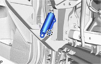
Disengage the claw to remove the glove compartment door stopper sub-assembly.
53601
20.DISCONNECT HOOD LOCK CONTROL LEVER SUB-ASSEMBLY
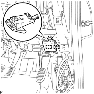
Disengage the claw and 2 guides, and disconnect the hood lock control lever sub-assembly.
55303B
21.REMOVE LOWER INSTRUMENT PANEL SUB-ASSEMBLY
Disengage each clamp.
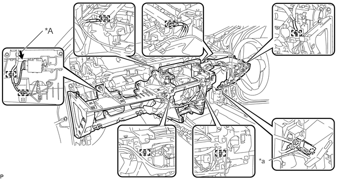
| *A | w/ Rain Sensor | - | - |
| *a | DLC3 | - | - |
w/ Rain Sensor:
Disconnect each connector.
Disengage the 2 claws and disconnect the DLC3.
Remove the 2 bolts <A> or <B>, 8 screws <D>, screw <E> or <F> and lower instrument panel sub-assembly.
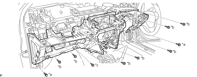
| *a | Bolt <A> or <B> | *b | Screw <D> |
| *c | Screw <E> or <F> | - | - |