DRIVE SHAFT / PROPELLER SHAFT FRONT DRIVE SHAFT ASSEMBLY(for 1ZR-FE, 2ZR-FE) INSTALLATION
CAUTION / NOTICE / HINT
- HINT:
- ·
Use the same procedure for the RH side and LH side.
·The following procedure is for the LH side.
PROCEDURE

 43420G
1.INSTALL FRONT DRIVE SHAFT HOLE SNAP RING
43420G
1.INSTALL FRONT DRIVE SHAFT HOLE SNAP RING
Install a new front drive shaft hole snap ring.
- NOTICE:
-
Face the end gap of the front drive shaft hole snap ring downward.
43420
2.INSTALL FRONT DRIVE SHAFT ASSEMBLY LH
for CVT:
Coat the splines of the front drive inboard joint assembly with Toyota genuine CVT fluid FE.
Coat the lip of the front drive shaft oil seal LH with MP grease.
for Automatic Transaxle:
Coat the splines of the front drive inboard joint assembly with ATF WS.
Coat the lip of the front drive shaft oil seal LH with MP grease.
for Manual Transaxle:
Coat the splines of the front drive inboard joint assembly with gear oil.
Coat the lip of the front drive shaft oil seal LH with MP grease.
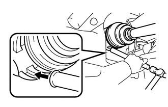
Align the inboard joint splines, and using a brass bar and a hammer, install the front drive shaft assembly LH.
- NOTICE:
- ·
Face the end gap of the front drive shaft hole snap ring downward.
·Do not damage the front drive shaft oil seal LH.
·Do not damage the front axle inboard joint boot.
·Make sure to center the front drive shaft assembly LH during installation to prevent damage to the front drive shaft hole snap ring.
- HINT:
-
Confirm whether the drive shaft is securely driven in by checking the reaction force and sound.
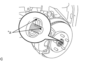
| *a | Matchmark |
Align the matchmarks and install the front drive shaft assembly LH to the front axle hub sub-assembly.
- NOTICE:
- ·
Do not push the front axle assembly further out of the vehicle than is necessary.
·Be careful not to damage the front axle outboard joint boot.
·Check for any foreign matter on the speed sensor rotor and insertion part.
·Do not damage the speed sensor rotor.
43410
3.INSTALL FRONT DRIVE SHAFT ASSEMBLY RH
- HINT:
-
Perform the same procedure as for the LH side.
48069
4.CONNECT FRONT LOWER NO. 1 SUSPENSION ARM SUB-ASSEMBLY
48810
5.INSTALL FRONT STABILIZER LINK ASSEMBLY
45047
6.CONNECT TIE ROD END SUB-ASSEMBLY
89543
7.INSTALL FRONT SPEED SENSOR
43502H
8.INSTALL FRONT AXLE SHAFT NUT
Clean the threaded parts on the front drive shaft assembly and a new front axle shaft nut using non-residue solvent.
- NOTICE:
- ·
Be sure to perform this work even when using a new front drive shaft assembly.
·Keep the threaded parts free of oil and foreign matter.
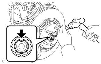
Using a 30 mm socket wrench, install the front axle shaft nut.
- Torque:
- 216 N*m (2203 kgf*cm, 159 ft.*lbf)
- HINT:
-
Keep depressing the brake pedal to prevent the drive shaft from rotating.
Using a chisel and a hammer, stake the front axle shaft nut.
9.ADJUST CONTINUOUSLY VARIABLE TRANSAXLE FLUID (for CVT)
10.ADD AUTOMATIC TRANSAXLE FLUID (for Automatic Transaxle)
11.CHECK FLUID LEVEL (for Automatic Transaxle)
12.ADD MANUAL TRANSAXLE OIL (for Manual Transaxle)
13.INSPECT FOR OIL LEAK (for Manual Transaxle)
51442C
14.INSTALL ENGINE UNDER COVER LH
51441C
15.INSTALL ENGINE UNDER COVER RH
16.INSTALL FRONT WHEELS
17.INSPECT AND ADJUST FRONT WHEEL ALIGNMENT
18.CHECK FOR SPEED SENSOR SIGNAL