AXLE AND DIFFERENTIAL FRONT AXLE HUB INSTALLATION
CAUTION / NOTICE / HINT
- HINT:
- ·
Use the same procedure for the RH side and LH side.
·The following procedure is for the LH side.
PROCEDURE

 43502E
1.INSTALL FRONT AXLE HUB BEARING
43502E
1.INSTALL FRONT AXLE HUB BEARING
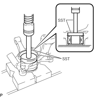
Using SST and a press, install a new front axle hub bearing to the steering knuckle.
- SST
- 09950-60020 (09951-00720)
09950-70010 (09951-07100)
47782
2.INSTALL FRONT DISC BRAKE DUST COVER
Install the front disc brake dust cover to the steering knuckle with the 3 bolts.
- Torque:
- 8.3 N*m (85 kgf*cm, 73 in.*lbf)
43502C
3.INSTALL FRONT AXLE HUB SUB-ASSEMBLY
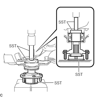
Using SST and a press, install the front axle hub sub-assembly to the steering knuckle.
- SST
- 09608-32010
09950-60010 (09951-00550)
09950-70010 (09951-07100)
43502G
4.INSTALL FRONT AXLE HUB HOLE SNAP RING
Using snap ring pliers, install a new front axle hub hole snap ring.
43340A
5.INSTALL FRONT LOWER BALL JOINT ASSEMBLY
6.INSTALL FRONT AXLE ASSEMBLY
Install the front axle assembly to the front shock absorber assembly with the 2 bolts and 2 nuts.
- Torque:
- 240 N*m (2447 kgf*cm, 177 ft.*lbf)
- NOTICE:
-
When installing the nuts, keep the bolts from rotating.
- HINT:
-
Insert the bolts from the front of the vehicle.
43420
7.CONNECT FRONT DRIVE SHAFT ASSEMBLY
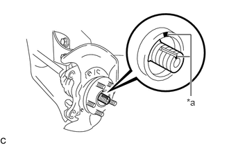
| *a | Matchmark |
Align the matchmarks on the front drive shaft assembly and front axle hub sub-assembly, and connect the front drive shaft assembly to the front axle hub sub-assembly.
- NOTICE:
-
Be careful not to damage the drive shaft boot.
48069
8.CONNECT FRONT LOWER NO. 1 SUSPENSION ARM SUB-ASSEMBLY
Connect the front lower No. 1 suspension arm sub-assembly to the front lower ball joint assembly with the bolt and 2 nuts.
- Torque:
- 89 N*m (908 kgf*cm, 66 ft.*lbf)
45047
9.CONNECT TIE ROD END SUB-ASSEMBLY
43512
10.INSTALL FRONT DISC
11.INSTALL FRONT DISC BRAKE CALIPER ASSEMBLY
43502H
12.TEMPORARILY INSTALL FRONT AXLE SHAFT NUT
Clean the threaded parts on the front drive shaft assembly and a new front axle shaft nut using non-residue solvent.
- NOTICE:
- ·
Be sure to perform this work even when using a new drive shaft.
·Keep the threaded parts free of oil and foreign matter.
Using a 30 mm socket wrench, while applying the brakes, temporarily install the front axle shaft nut.
- Torque:
- 216 N*m (2203 kgf*cm, 159 ft.*lbf)
- NOTICE:
-
Stake the front axle shaft nut after inspecting for looseness and runout in the following steps.
- HINT:
-
Keep depressing the brake pedal to prevent the drive shaft from rotating.
13.SEPARATE FRONT DISC BRAKE CALIPER ASSEMBLY
43512
14.REMOVE FRONT DISC
Click hereBrake>BRAKE (FRONT)>FRONT BRAKE>REMOVAL
15.INSPECT FRONT AXLE HUB BEARING LOOSENESS
16.INSPECT FRONT AXLE HUB RUNOUT
43512
17.INSTALL FRONT DISC
18.INSTALL FRONT DISC BRAKE CALIPER ASSEMBLY
47313J
19.INSTALL FRONT FLEXIBLE HOSE (w/o ABS)
Install the front flexible hose to the front shock absorber assembly with the bolt.
- Torque:
- 29 N*m (296 kgf*cm, 21 ft.*lbf)
- NOTICE:
-
Do not twist the front flexible hose when installing it.
89543
20.INSTALL FRONT SPEED SENSOR (w/ ABS)
Install the front speed sensor wire and front flexible hose to the front shock absorber assembly with the bolt.
- Torque:
- 29 N*m (296 kgf*cm, 21 ft.*lbf)
- NOTICE:
-
Do not twist the front speed sensor and front flexible hose when installing them.
- HINT:
-
Install the front speed sensor harness bracket first and then the front flexible hose bracket.
Install the front speed sensor to the steering knuckle with the bolt.
- Torque:
- 8.5 N*m (87 kgf*cm, 75 in.*lbf)
- NOTICE:
-
Do not twist the front speed sensor when installing it.
43502H
21.STAKE FRONT AXLE SHAFT NUT
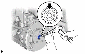
Using a chisel and hammer, stake the front axle shaft nut.
22.INSTALL FRONT WHEEL
23.INSPECT AND ADJUST FRONT WHEEL ALIGNMENT
24.CHECK FOR SPEED SENSOR SIGNAL (w/ ABS)