AXLE AND DIFFERENTIAL FRONT AXLE HUB ON-VEHICLE INSPECTION
CAUTION / NOTICE / HINT
- HINT:
- ·
Use the same procedure for the RH side and LH side.
·The following procedure is for the LH side.
PROCEDURE

 1.REMOVE FRONT WHEEL
2.SEPARATE FRONT DISC BRAKE CALIPER ASSEMBLY
Remove the 2 bolts and separate the front disc brake caliper assembly from the steering knuckle.
- NOTICE:
-
Use wire or an equivalent tool to keep the front disc brake caliper assembly from hanging by the front flexible hose.
43512
3.REMOVE FRONT DISC
Click hereBrake>BRAKE (FRONT)>FRONT BRAKE>REMOVAL
4.INSPECT FRONT AXLE HUB BEARING LOOSENESS
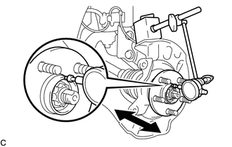
Using a dial indicator, check for looseness near the center of the front axle hub sub-assembly.
- Maximum Looseness:
0.03 mm (0.00118 in.)
- NOTICE:
- ·
Ensure that the dial indicator is set perpendicular to the measurement surface.
·Keep the magnet of the dial indicator away from the front speed sensor (w/ ABS).
- HINT:
-
If the looseness exceeds the maximum, replace the front axle hub bearing.
5.INSPECT FRONT AXLE HUB RUNOUT
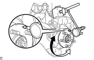
Using a dial indicator, check for runout on the surface of the front axle hub sub-assembly outside the front axle hub bolts.
- Maximum Runout:
0.03 mm (0.00118 in.)
- NOTICE:
- ·
Ensure that the dial indicator is set perpendicular to the measurement surface.
·Make sure to set the tip of the dial indicator towards the outside of the front axle hub bolts.
·Keep the magnet of the dial indicator away from the front speed sensor (w/ ABS).
- HINT:
-
If the runout exceeds the maximum, replace the front axle hub sub-assembly.
43512
6.INSTALL FRONT DISC
7.INSTALL FRONT DISC BRAKE CALIPER ASSEMBLY
Install the front disc brake caliper assembly to the steering knuckle with the 2 bolts.
- Torque:
- 106.8 N*m (1089 kgf*cm, 79 ft.*lbf)
- NOTICE:
-
Do not twist the front flexible hose when installing the front disc brake caliper assembly.
8.INSTALL FRONT WHEEL