STEERING GEAR / LINKAGE STEERING GEAR INSTALLATION
PROCEDURE

 45047
1.INSTALL TIE ROD END SUB-ASSEMBLY LH
45047
1.INSTALL TIE ROD END SUB-ASSEMBLY LH
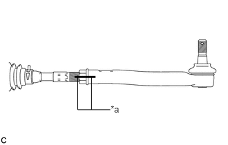
| *a | Matchmark |
Install the lock nut and tie rod end sub-assembly LH to the steering gear assembly until the matchmarks are aligned.
- HINT:
-
After adjusting the toe-in, tighten the lock nut.
45046
2.INSTALL TIE ROD END SUB-ASSEMBLY RH
- HINT:
-
Perform the same procedure as for the LH side.
3.INSTALL STEERING LINK ASSEMBLY
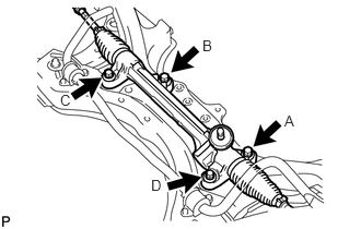
Install the steering link assembly to the front suspension crossmember sub-assembly with the 4 bolts.
Temporarily tighten the bolt (A).
Tighten the bolts in the order of (B), (C), (D), and then (A).
- Torque:
- 58 N*m (591 kgf*cm, 43 ft.*lbf)
45221
4.INSTALL STEERING INTERMEDIATE SHAFT
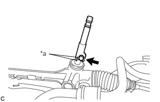
| *a | Matchmark |
Align the matchmarks and install the steering intermediate shaft to the steering link assembly.
Install a new bolt.
- Torque:
- 35 N*m (357 kgf*cm, 26 ft.*lbf)
45025D
5.INSTALL NO. 1 STEERING COLUMN HOLE COVER SUB-ASSEMBLY
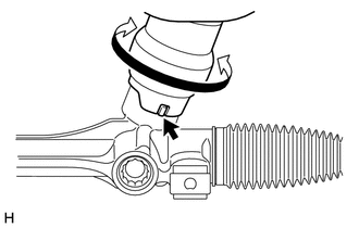
Align the protrusion of the steering link assembly with the cutout of the No. 1 steering column hole cover sub-assembly, and install the No. 1 steering column hole cover sub-assembly to the steering link assembly.
- NOTICE:
-
Move the No. 1 steering column hole cover sub-assembly as shown in the illustration and check that it is securely installed.
51201
6.INSTALL FRONT SUSPENSION CROSSMEMBER SUB-ASSEMBLY
48069
7.CONNECT FRONT LOWER NO. 1 SUSPENSION ARM SUB-ASSEMBLY LH
48068
8.CONNECT FRONT LOWER NO. 1 SUSPENSION ARM SUB-ASSEMBLY RH
- HINT:
-
Perform the same procedure as for the LH side.
48810
9.INSTALL FRONT STABILIZER LINK ASSEMBLY LH
48820B
10.INSTALL FRONT STABILIZER LINK ASSEMBLY RH
- HINT:
-
Perform the same procedure as for the LH side.
45047
11.CONNECT TIE ROD END SUB-ASSEMBLY LH
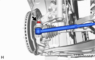
Connect the tie rod end sub-assembly LH to the steering knuckle with the nut.
- Torque:
- 49 N*m (500 kgf*cm, 36 ft.*lbf)
- NOTICE:
- ·
Do not damage the ball joint dust cover.
·Further tighten the nut up to 60° if the holes for the cotter pin are not aligned.
Install a new cotter pin.
45046
12.CONNECT TIE ROD END SUB-ASSEMBLY RH
- HINT:
-
Perform the same procedure as for the LH side.
45025D
13.CONNECT NO. 1 STEERING COLUMN HOLE COVER SUB-ASSEMBLY
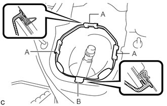
Install the clip (B) as shown in the illustration and engage the 3 clips (A) to the body to connect the No. 1 steering column hole cover sub-assembly.
- NOTICE:
-
Make sure that the lip of the No. 1 steering column hole cover sub-assembly is not damaged.
45260
14.CONNECT NO. 2 STEERING INTERMEDIATE SHAFT ASSEMBLY
45259A
15.INSTALL COLUMN HOLE COVER SILENCER SHEET
16.INSTALL FRONT WHEELS
17. STABILIZE SUSPENSION
51442C
18.INSTALL ENGINE UNDER COVER LH
51441C
19.INSTALL ENGINE UNDER COVER RH
20.INSPECT AND ADJUST FRONT WHEEL ALIGNMENT