2ZR-FE ENGINE CONTROL SFI SYSTEM Brake Override System
DESCRIPTION
When the vehicle is being driven, depressing the accelerator pedal sensor assembly and brake pedal will activate the brake override system to restrict driving torque. The conditions for activating the brake override system as well as the items that are controlled are explained below.
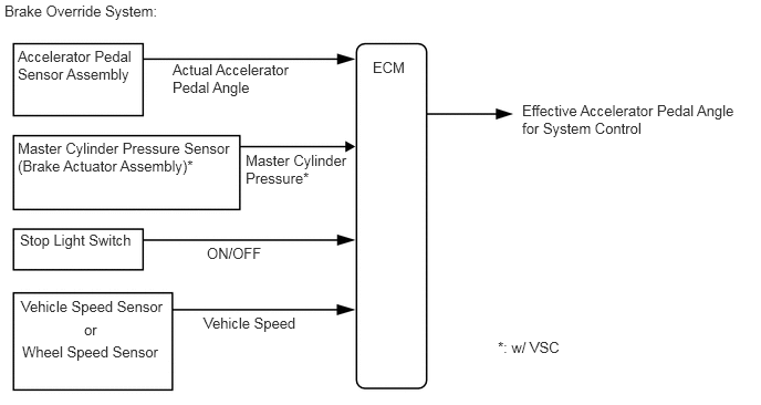
- Activation Conditions:
- ·
Vehicle is running at or above the specified speed.
·When the accelerator pedal and brake pedal are depressed.
- NOTICE:
-
The vehicle may not enter the brake override system control due to the relation of the accelerator pedal angle and the vehicle's speed.
- Items Controlled:
- ·
Driving torque is restricted.
- HINT:
-
When this control is activated, the accelerator opening value is forcibly reduced to a fixed value. Therefore, the Accelerator Position value in the Data List is fixed regardless of the actual accelerator opening value (Accel Sens. No.1 Volt %).
- Deactivation Conditions:
- ·
When the brake pedal or the accelerator pedal returns to some degree.
CAUTION / NOTICE / HINT
- Inspection Method
-
Example:
-
Drive at 10 km/h (6.25 mph), depress the accelerator pedal by 1/2 to 3/4 and keep it in that position. Under these conditions, if the engine speed decreases to 1000 rpm when the brake pedal is depressed, then the brake override system has been activated.
- CAUTION:
-
When carrying out the inspection, use a place where you are able to carry it out safely and also pay close attention to your surroundings.
-
Also, when driving make absolutely sure that all road traffic laws, such as speed limits, are observed.
- HINT:
- ·
Under normal conditions, the Accelerator Position value changes in response to the Accel Sens. No.1 Volt % value. For more information on the numerical values, refer to the Data List.
Click hereEngine / Hybrid System>2ZR-FE ENGINE CONTROL>SFI SYSTEM>DATA LIST / ACTIVE TEST
·If the Accelerator Position and Accel Sens. No.1 Volt % values in the Data List diverge and the Accelerator Position value in the Data List is fixed even though Accel Sens. No.1 Volt % is changing, check that this control is activated (use the GTS data saving function to record data while driving the vehicle and then confirm it after driving is completed).
- NOTICE:
-
The brake override system restricts driving torque if the brake pedal is depressed when driving with the accelerator pedal depressed. If a customer reports experiencing loss of torque after the accelerator and brake pedals have both been intentionally depressed, explain to the customer that this is not a malfunction, and that the customer should avoid depressing both the accelerator and brake pedals at the same time.
-
Example: While operating the accelerator pedal, the customer uses their left foot to operate the brake pedal.
PROCEDURE
Connect the GTS to the DLC3.
Turn the ignition switch to ON and turn the GTS on.
Enter the following menus: System Select / Health Check.
Check the DTCs.
- Result:
Result Proceed to DTC is not output (w/ VSC) A DTC is not output (w/o VSC) B DTCs are output C
A
B
C
Connect the GTS to the DLC3.
Start the engine and turn the GTS on.
Enter the following menus: Chassis / ABS/VSC/TRC / Data List / Master Cylinder Sensor.
- Chassis > ABS/VSC/TRC > Data List
-
Tester Display Master Cylinder Sensor - 50003 105 9
Read the value displayed on the GTS.
| GTS Display | Measurement Item/Range | Normal Condition |
|---|---|---|
| Master Cylinder Sensor | Master cylinder pressure sensor reading/
Min.: 0.00 V, Max.: 5.00 V |
·
Brake pedal released: 0.30 to 0.80 V ·
Reading increases when brake pedal is depressed |
Check that the brake fluid pressure value of the "Maser Cylinder Sensor" observed on the GTS changes when the brake pedal is depressed.
- OK:
When the pedal is depressed, the voltage displayed on the GTS increases.
- Result:
Proceed to OK NG
OK
NG
Connect the GTS to the DLC3.
Turn the ignition switch to ON and turn the GTS on.
Enter the following menus: Powertrain / Engine and ECT / Data List / All Data / Stop Light Switch and ST1.
- Powertrain > Engine and ECT > Data List
-
Tester Display Stop Light Switch ST1 - 50003 234 117,294
Check the Data List indication when the brake pedal is depressed and released.
- OK:
GTS Display Condition Specified Condition Stop Light Switch Brake pedal released OFF Brake pedal depressed ON ST1 Brake pedal released OFF Brake pedal depressed ON
- Result:
Proceed to OK NG
OK
NG
Inspect and adjust the brake pedal sub-assembly.
Click hereBrake>BRAKE SYSTEM (OTHER)>BRAKE PEDAL>ADJUSTMENT
- HINT:
-
If the stop light switch assembly turns on too late, the start of brake override system control may be delayed; if it turns ON too soon, brake override system control may begin too early, so conduct inspection of the brake pedal sub-assembly and stop light switch assembly.
- Result:
Proceed to OK NG
OK
NG
Connect the GTS to the DLC3.
Turn the ignition switch to ON and turn the GTS on.
Enter the following menus: Powertrain / Engine and ECT / Data List / All Data / Accel Sens. No.1 Volt % and Accel Sens. No.2 Volt %.
- Powertrain > Engine and ECT > Data List
-
Tester Display Accel Sens. No.1 Volt % Accel Sens. No.2 Volt % - 50003 234 15,16
Read the value displayed on the GTS.
- OK:
GTS Display Condition Specified Condition Accel Sens. No.1 Volt % Accelerator Pedal
Released → Depressed → ReleasedValues smoothly change following accelerator pedal operation Accel Sens. No.2 Volt %
- HINT:
-
For numerical values of Accel Sens. No.1 Volt % and Accel Sens. No.2 Volt %, refer to the Data List.
-
Click hereEngine / Hybrid System>2ZR-FE ENGINE CONTROL>SFI SYSTEM>DATA LIST / ACTIVE TEST
- Result:
Proceed to OK NG
OK
NG
Connect the GTS to the DLC3.
Turn the ignition switch to ON and turn the GTS on.
Start the engine.
Enter the following menus: Powertrain / Engine and ECT / Data List / All Data / Vehicle Speed.
- Powertrain > Engine and ECT > Data List
-
Tester Display Vehicle Speed - 50003 234 10
Read the value displayed on the GTS.
- Standard:
GTS Display Condition Specified Condition Vehicle Speed Vehicle stopped, engine running 0 km/h (0 mph) Vehicle being driven at constant speed between 16.1 to 64.4 km/h (10 to 40 mph) No large fluctuations when driving at a constant speed
- CAUTION:
-
When performing a drive test, obey all speed limits and traffic laws.
- HINT:
-
Data can be captured relatively easily by using the snapshot function in the Data List. Confirm the data after performing the drive test.
- Result:
Proceed to OK NG
OK
NG
Connect the GTS to the DLC3.
Turn the ignition switch to ON and turn the GTS on.
Start the engine.
Enter the following menus: Chassis / ABS/VSC/TRC / Data List / FR Wheel Speed, FL Wheel Speed, RR Wheel Speed and RL Wheel Speed.
- Chassis > ABS/VSC/TRC > Data List
-
Tester Display FR Wheel Speed FL Wheel Speed RR Wheel Speed RL Wheel Speed - 50003 105 1,2,3,4
Read the value displayed on the GTS.
- Standard:
GTS Display Condition Specified Condition FR Wheel Speed
FL Wheel Speed
RR Wheel Speed
RL Wheel SpeedVehicle stopped, engine running 0 km/h (0 mph) Vehicle being driven at constant speed between 16.1 to 64.4 km/h (10 to 40 mph) No large fluctuations when driving at a constant speed
- CAUTION:
-
When performing a drive test, obey all speed limits and traffic laws.
- HINT:
-
Data can be captured relatively easily by using the snapshot function in the Data List. Confirm the data after performing the drive test.
- Result:
Proceed to OK NG
OK
NG