BRAKE CONTROL / DYNAMIC CONTROL SYSTEMS VEHICLE STABILITY CONTROL SYSTEM Brake Warning Light Remains ON
DESCRIPTION
The skid control ECU (brake actuator assembly) is connected to the combination meter assembly via CAN communication.
If any of the following is detected, the brake warning light remains on:
The skid control ECU (brake actuator assembly) connector is disconnected from the skid control ECU (brake actuator assembly).
The brake fluid level is insufficient.
The parking brake is applied.
EBD operation is not possible.
WIRING DIAGRAM
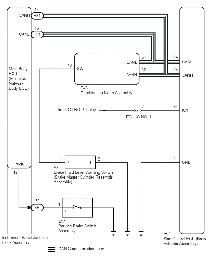
CAUTION / NOTICE / HINT
- NOTICE:
- ·
When replacing the skid control ECU (brake actuator assembly), perform zero point calibration.
Click hereBrake>BRAKE CONTROL / DYNAMIC CONTROL SYSTEMS>VEHICLE STABILITY CONTROL SYSTEM>CALIBRATION
·Inspect the fuses for circuits related to this system before performing the following procedure.
·Before performing this procedure, depress the brake pedal and confirm that the stop lights illuminate.
PROCEDURE
Check if CAN communication system DTCs are output.
Click herePower Source / Network>NETWORKING>CAN COMMUNICATION SYSTEM>DIAGNOSIS SYSTEM
- Result:
Result Proceed to DTCs are not output. A DTCs are output. B
A
B
Click herePower Source / Network>NETWORKING>CAN COMMUNICATION SYSTEM>HOW TO PROCEED WITH TROUBLESHOOTING
Check if the skid control ECU (brake actuator assembly) connector is securely connected.
- OK:
The connector is securely connected.
- Result:
Proceed to OK NG
OK
NG
Check the battery voltage.
- Standard Voltage:
11 to 14 V
- Result:
Proceed to OK NG
OK
NG
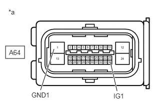
| *a | Front view of wire harness connector
(to Skid Control ECU (Brake Actuator Assembly)) |
Disconnect the A64 skid control ECU (brake actuator assembly) connector.
Measure the voltage according to the value(s) in the table below.
- Standard Voltage:
Tester Connection Condition Specified Condition A64-34 (IG1) - Body ground Engine switch on (IG) 11 to 14 V A64-34 (IG1) - A64-1 (GND1) Engine switch on (IG) 11 to 14 V
- Result:
Proceed to OK NG
OK
NG
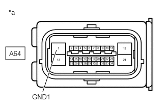
| *a | Front view of wire harness connector
(to Skid Control ECU (Brake Actuator Assembly)) |
Turn the engine switch off.
Measure the resistance according to the value(s) in the table below.
- Standard Resistance:
Tester Connection Condition Specified Condition A64-1 (GND1) - Body ground Always Below 1 Ω
- Result:
Proceed to OK NG
OK
NG
Reconnect the A64 skid control ECU (brake actuator assembly) connector.
Connect the GTS to the DLC3.
Turn the engine switch on (IG).
Select the Data List using the GTS.
- Chassis > ABS/VSC/TRC > Data List
-
Tester Display Measurement Item Range Normal Condition Diagnostic Note Parking Brake SW Parking brake switch assembly ON or OFF ON: Parking brake applied
OFF: Parking brake released-
- Chassis > ABS/VSC/TRC > Data List
-
Tester Display Parking Brake SW - 50003 105 38
Using the GTS, check that the switch condition displayed on the GTS changes according to the parking brake operation.
- OK:
The GTS displays ON or OFF according to parking brake operation.
- Result:
Proceed to OK NG
OK
NG
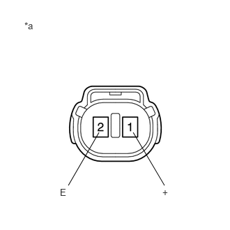
| *a | Component without harness connected
(Brake Fluid Level Warning Switch (Brake Master Cylinder Reservoir Assembly)) |
Turn the engine switch off.
Remove the reservoir filler cap and strainer.
Disconnect the A8 brake fluid level warning switch (brake master cylinder reservoir assembly) connector.
Measure the resistance according to the value(s) in the table below.
- HINT:
-
A float is located inside the reservoir. Its position changes according to the brake fluid level.
- Standard Resistance:
Tester Connection Condition Specified Condition 1 (+) - 2 (E) Switch OFF (Float up) 1.9 to 2.1 kΩ 1 (+) - 2 (E) Switch ON (Float down) Below 1 Ω
- HINT:
-
If the switch condition is normal, adjust the brake fluid level to the MAX level.
- Result:
Proceed to OK NG
OK
NG
Disconnect the E43 combination meter assembly connector.
Measure the resistance according to the value(s) in the table below.
- Standard Resistance:
Tester Connection Condition Specified Condition E43-12 (SW) - A8-1 (+) Always Below 1 Ω E43-12 (SW) or A8-1 (+) - Body ground Always 10 kΩ or higher A8-2 (E) - Body ground Always Below 1 Ω
- Result:
Proceed to OK NG
OK
NG
Reconnect the A8 brake fluid level warning switch (brake master cylinder reservoir assembly) connector.
Reconnect the E43 combination meter assembly connector.
Select the Data List on the GTS.
- Chassis > ABS/VSC/TRC > Data List
-
Tester Display Measurement Item Range Normal Condition Diagnostic Note Brake Warning Light Brake warning light ON or OFF ON: Warning light on
OFF: Warning light off-
- Chassis > ABS/VSC/TRC > Data List
-
Tester Display Brake Warning Light - 50003 105 52
Check the GTS display condition of the brake warning light.
- Result:
Result Proceed to ON is displayed. A OFF is displayed. B
- HINT:
-
If troubleshooting has been carried out according to Problem Symptoms Table, refer back to the table and proceed to the next step before replacing parts.
A
B
Click hereVehicle Interior>METER / GAUGE / DISPLAY>METER / GAUGE SYSTEM>HOW TO PROCEED WITH TROUBLESHOOTING
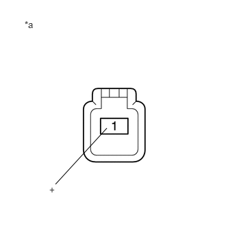
| *a | Component without harness connected
(Parking Brake Switch Assembly) |
Turn the engine switch off.
Disconnect the L17 parking brake switch assembly connector.
Measure the resistance according to the value(s) in the table below.
- Standard Resistance:
Tester Connection Condition Specified Condition 1 (+) - Body ground Switch ON
(Switch pin free)Below 1 Ω 1 (+) - Body ground Switch OFF
(Switch pin pushed in)10 kΩ or higher
- Result:
Proceed to OK NG
OK
NG
Disconnect the 3E instrument panel junction block assembly connector.
Measure the resistance according to the value(s) in the table below.
- Standard Resistance:
Tester Connection Condition Specified Condition 3E-30 - L17-1 (+) Always Below 1 Ω 3E-30 or L17-1 (+) - Body ground Always 10 kΩ or higher
- Result:
Proceed to OK NG
OK
NG
Remove the main body ECU (multiplex network body ECU) from the instrument panel junction block assembly.
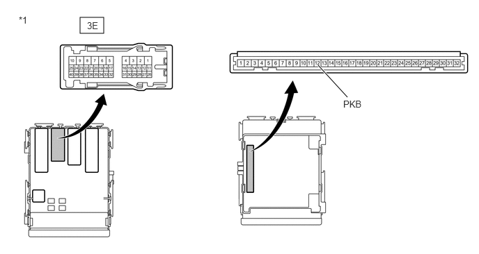
| *1 | Instrument Panel Junction Block Assembly | - | - |
Measure the resistance according to the value(s) in the table below.
- Standard Resistance:
Tester Connection Condition Specified Condition 3E-30 - 12 (PKB) Always Below 1 Ω 3E-30 or 12 (PKB) - Body ground Always 10 kΩ or higher
- HINT:
-
If troubleshooting has been carried out according to Problem Symptoms Table, refer back to the table and proceed to the next step before replacing the parts.
- Result:
Proceed to OK NG
OK
NG