BRAKE CONTROL / DYNAMIC CONTROL SYSTEMS VEHICLE STABILITY CONTROL SYSTEM C1407 Open or Short in Rear Speed Sensor RH Circuit C1408 Open or Short in Rear Speed Sensor LH Circuit
DESCRIPTION
Refer to DTCs C1415 and C1416.
Click hereBrake>BRAKE CONTROL / DYNAMIC CONTROL SYSTEMS>VEHICLE STABILITY CONTROL SYSTEM>C1273
| DTC No. | Detection Item | DTC Detection Condition | Trouble Area |
|---|---|---|---|
| C1407 | Open or Short in Rear Speed Sensor RH Circuit | Either of the following is detected:
1.
An open in the speed sensor signal circuit continues for 0.5 seconds or more. 2.
With the IG1 terminal voltage 9.5 V or more, the sensor power supply voltage decreases for 0.5 seconds or more. |
·
Rear speed sensor RH (rear axle hub and bearing assembly RH) ·
Speed sensor circuit ·
Skid control ECU (brake actuator assembly) |
| C1408 | Open or Short in Rear Speed Sensor LH Circuit | Either of the following is detected:
1.
An open in the speed sensor signal circuit continues for 0.5 seconds or more. 2.
With the IG1 terminal voltage 9.5 V or more, the sensor power supply voltage decreases for 0.5 seconds or more. |
·
Rear speed sensor LH (rear axle hub and bearing assembly LH) ·
Speed sensor circuit ·
Skid control ECU (brake actuator assembly) |
- HINT:
-
Even after the trouble areas are repaired, the ABS warning light will not go off unless the following operations are performed:
- 1.
Drive the vehicle at 20 km/h (12 mph) for 30 seconds or more and check that the ABS warning light goes off.
2.Clear the DTCs.
- HINT:
- ·
DTC C1407 is for the rear speed sensor RH.
·DTC C1408 is for the rear speed sensor LH.
WIRING DIAGRAM
Refer to DTCs C1415 and C1416.
Click hereBrake>BRAKE CONTROL / DYNAMIC CONTROL SYSTEMS>VEHICLE STABILITY CONTROL SYSTEM>C1273
CAUTION / NOTICE / HINT
- NOTICE:
-
When replacing the skid control ECU (brake actuator assembly), perform zero point calibration.
-
Click hereBrake>BRAKE CONTROL / DYNAMIC CONTROL SYSTEMS>VEHICLE STABILITY CONTROL SYSTEM>CALIBRATION
PROCEDURE
Using the GTS, check for any momentary interruption in the wire harness and connector corresponding to a DTC.
- Chassis > ABS/VSC/TRC > Data List
-
Tester Display Measurement Item Range Normal Condition Diagnostic Note RR Speed Sensor Voltage Open Rear speed sensor RH voltage open detection Error or Normal Error: Momentary interruption
Normal: Normal- RL Speed Sensor Voltage Open Rear speed sensor LH voltage open detection Error or Normal Error: Momentary interruption
Normal: Normal-
- Chassis > ABS/VSC/TRC > Data List
-
Tester Display RR Speed Sensor Voltage Open RL Speed Sensor Voltage Open - 50003 105 296,297
- OK:
There are no momentary interruptions.
- HINT:
-
Perform the above inspection before removing the sensor and connector.
- Result:
Proceed to OK NG
OK
NG
Turn the engine switch off.
Connect the GTS to the DLC3.
Start the engine.
Select the Data List using the GTS.
- Chassis > ABS/VSC/TRC > Data List
-
Tester Display Measurement Item Range Normal Condition Diagnostic Note RR Wheel Speed Rear wheel speed sensor RH reading Min.: 0 km/h (0 mph), Max.: 326.4 km/h (203 mph) Vehicle stopped: 0 km/h (0 mph) When driving at constant speed: No large fluctuations RL Wheel Speed Rear wheel speed sensor LH reading Min.: 0 km/h (0 mph), Max.: 326.4 km/h (203 mph) Vehicle stopped: 0 km/h (0 mph) When driving at constant speed: No large fluctuations
- Chassis > ABS/VSC/TRC > Data List
-
Tester Display RR Wheel Speed RL Wheel Speed - 50003 105 3,4
Check the speed value output from the speed sensor displayed on the GTS.
- HINT:
-
Factors that affect the indicated vehicle speed include tire size, tire pressure, and tire wear. The speed indicated on the speedometer has an allowable margin of error. This can be tested using a speedometer tester (calibrated chassis dynamometer). For details about testing and the margin of error, see the reference chart.
-
Click hereVehicle Interior>METER / GAUGE / DISPLAY>METER / GAUGE SYSTEM>ON-VEHICLE INSPECTION
- OK:
The speed value output from the speed sensor displayed on the GTS is similar to the speed indicated on the speedometer.
- Result:
Proceed to OK NG
OK
NG
Turn the engine switch off.
Clear the DTCs.
Click hereBrake>BRAKE CONTROL / DYNAMIC CONTROL SYSTEMS>VEHICLE STABILITY CONTROL SYSTEM>DTC CHECK / CLEAR
- Chassis > ABS/VSC/TRC > Clear DTCs
- 50002 105
Turn the engine switch off.
Start the engine.
Perform a road test.
Check if the same DTC is output.
Click hereBrake>BRAKE CONTROL / DYNAMIC CONTROL SYSTEMS>VEHICLE STABILITY CONTROL SYSTEM>DTC CHECK / CLEAR
- Chassis > ABS/VSC/TRC > Trouble Codes
- 50001 105
- Result:
Result Proceed to DTCs C1407 and C1408 are not output. A DTCs C1407 and/or C1408 are output. B
- HINT:
-
If troubleshooting has been carried out according to Problem Symptoms Table, refer back to the table and proceed to the next step before replacing parts.
A
Click hereGeneral>INTRODUCTION>HOW TO TROUBLESHOOT ECU CONTROLLED SYSTEMS>HOW TO PROCEED WITH TROUBLESHOOTING
B
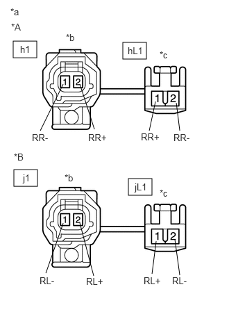
| *A | RH |
| *B | LH |
| *a | Front view of Skid Control Sensor Wire |
| *b | Front view of wire harness connector
(to Sensor Side Connector) |
| *c | Front view of wire harness connector
(to Vehicle Side Connector) |
Turn the engine switch off.
Make sure that there is no looseness at the locking part and the connecting part of the connectors.
Remove the skid control sensor wire.
Measure the resistance according to the value(s) in the table below.
- Standard Resistance:
for RH Tester Connection Condition Specified Condition h1-2 (RR+) - hL1-1 (RR+) Always Below 1 Ω h1-2 (RR+) - hL1-2 (RR-) Always 10 kΩ or higher h1-2 (RR+) or hL1-1 (RR+) - Body ground Always 10 kΩ or higher h1-1 (RR-) - hL1-2 (RR-) Always Below 1 Ω h1-1 (RR-) - hL1-1 (RR+) Always 10 kΩ or higher h1-1 (RR-) or hL1-2 (RR-) - Body ground Always 10 kΩ or higher
for LH Tester Connection Condition Specified Condition j1-2 (RL+) - jL1-1 (RL+) Always Below 1 Ω j1-2 (RL+) - jL1-2 (RL-) Always 10 kΩ or higher j1-2 (RL+) or jL1-1 (RL+) - Body ground Always 10 kΩ or higher j1-1 (RL-) - jL1-2 (RL-) Always Below 1 Ω j1-1 (RL-) - jL1-1 (RL+) Always 10 kΩ or higher j1-1 (RL-) or jL1-2 (RL-) - Body ground Always 10 kΩ or higher
- NOTICE:
-
Check the speed sensor signal after replacement.
-
Click hereBrake>BRAKE CONTROL / DYNAMIC CONTROL SYSTEMS>VEHICLE STABILITY CONTROL SYSTEM>TEST MODE PROCEDURE
- Result:
Proceed to OK NG
OK
NG
Make sure that there is no looseness at the locking part and the connecting part of the connector.
Disconnect the A64 skid control ECU (brake actuator assembly) connector.
Measure the resistance according to the value(s) in the table below.
- Standard Resistance:
for RH Tester Connection Condition Specified Condition A64-17 (RR+) - hL1-1 (RR+) Always Below 1 Ω A64-17 (RR+) or hL1-1 (RR+) - Body ground Always 10 kΩ or higher A64-16 (RR-) - hL1-2 (RR-) Always Below 1 Ω A64-16 (RR-) or hL1-2 (RR-) - Body ground Always 10 kΩ or higher
for LH Tester Connection Condition Specified Condition A64-5 (RL+) - jL1-1 (RL+) Always Below 1 Ω A64-5 (RL+) or jL1-1 (RL+) - Body ground Always 10 kΩ or higher A64-4 (RL-) - jL1-2 (RL-) Always Below 1 Ω A64-4 (RL-) or jL1-2 (RL-) - Body ground Always 10 kΩ or higher
- Result:
Proceed to OK NG
OK
NG
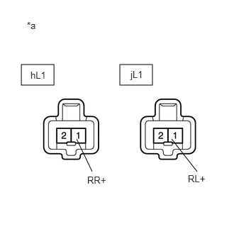
| *a | Front view of wire harness connector
(to Skid Control Sensor Wire) |
Reconnect the A64 skid control ECU (brake actuator assembly) connector.
Turn the engine switch on (IG).
Measure the voltage according to the value(s) in the table below.
- Standard Voltage:
for RH Tester Connection Condition Specified Condition hL1-1 (RR+) - Body ground Engine switch on (IG) 5.7 to 14 V
for LH Tester Connection Condition Specified Condition jL1-1 (RL+) - Body ground Engine switch on (IG) 5.7 to 14 V
- NOTICE:
-
Check the speed sensor signal after replacement.
-
Click hereBrake>BRAKE CONTROL / DYNAMIC CONTROL SYSTEMS>VEHICLE STABILITY CONTROL SYSTEM>TEST MODE PROCEDURE
- HINT:
- ·
The rear speed sensor rotor and rear speed sensor are incorporated into the rear axle hub and bearing assembly.
If the rear speed sensor rotor needs to be replaced, replace the rear axle hub and bearing assembly with rear speed sensor.
·If troubleshooting has been carried out according to Problem Symptoms Table, refer back to the table and proceed to the next step before replacing parts.
- Result:
Proceed to OK NG
OK
NG