BRAKE CONTROL / DYNAMIC CONTROL SYSTEMS VEHICLE STABILITY CONTROL SYSTEM TS and CG Terminal Circuit
DESCRIPTION
Connecting terminals TS and CG of the DLC3 causes the ECU to display Test Mode DTCs by blinking the ABS warning and slip indicator lights.
In Test Mode (signal check), a malfunction in a speed sensor that cannot be detected when the vehicle is stopped can be detected while driving.
Sensor check mode can be entered by connecting terminals TS and CG of the DLC3 and turning the engine switch from off to on (IG).
WIRING DIAGRAM
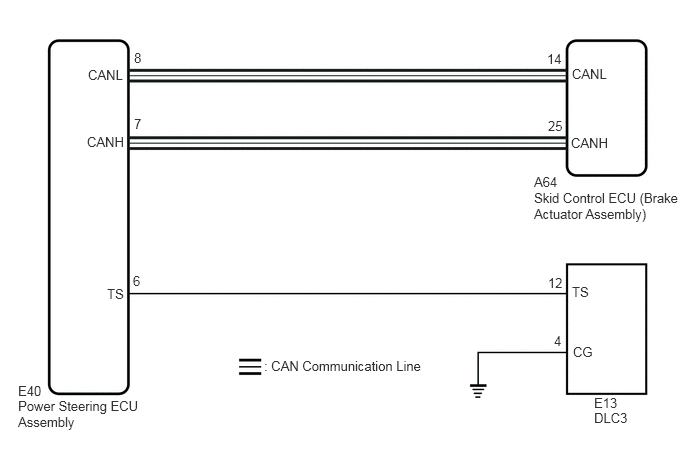
CAUTION / NOTICE / HINT
- NOTICE:
-
When replacing the skid control ECU (brake actuator assembly), perform zero point calibration.
-
Click hereBrake>BRAKE CONTROL / DYNAMIC CONTROL SYSTEMS>VEHICLE STABILITY CONTROL SYSTEM>CALIBRATION
PROCEDURE
Check if CAN communication system DTCs are output.
Click herePower Source / Network>NETWORKING>CAN COMMUNICATION SYSTEM>DIAGNOSIS SYSTEM
- Result:
Result Proceed to DTCs are not output. A DTCs are output. B
A
B
Click herePower Source / Network>NETWORKING>CAN COMMUNICATION SYSTEM>HOW TO PROCEED WITH TROUBLESHOOTING
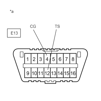
| *a | Front view of DLC3 |
Turn the engine switch on (IG).
Measure the voltage according to the value(s) in the table below.
- Standard Voltage:
Tester Connection Condition Specified Condition E13-12 (TS) - E13-4 (CG) Engine switch on (IG) 11 to 14 V
- Result:
Proceed to OK NG
OK
NG
| *a | Front view of DLC3 |
Turn the engine switch off.
Using SST, connect terminals TS and CG of the DLC3.
- SST
- 09843-18040
Check that the EPS warning light is blinking.
- OK:
The EPS warning light is blinking.
- HINT:
-
If troubleshooting has been carried out according to Problem Symptoms Table, refer back to the table and proceed to the next step before replacing parts.
- Result:
Proceed to OK NG
OK
NG
Turn the engine switch off.
Disconnect the E40 power steering ECU assembly connector.
Measure the resistance according to the value(s) in the table below.
- Standard Resistance:
Tester Connection Condition Specified Condition E13-12 (TS) - E40-6 (TS) Always Below 1 Ω E13-12 (TS) or E40-6 (TS) - Body ground Always 10 kΩ or higher
- Result:
Proceed to OK NG
OK
NG
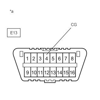
| *a | Front view of DLC3 |
Measure the resistance according to the value(s) in the table below.
- Standard Resistance:
Tester Connection Condition Specified Condition E13-4 (CG) - Body ground Always Below 1 Ω
- Result:
Proceed to OK NG
OK
NG
| *a | Front view of DLC3 |
Reconnect the E40 power steering ECU assembly connector.
Using SST, connect terminals TS and CG of the DLC3.
- SST
- 09843-18040
Check that the EPS warning light is blinking.
- OK:
The EPS warning light is blinking.
- HINT:
-
If troubleshooting has been carried out according to Problem Symptoms Table, refer back to the table and proceed to the next step before replacing parts.
- Result:
Proceed to OK NG
OK
NG