METER / GAUGE / DISPLAY METER / GAUGE SYSTEM Fuel Receiver Gauge Display Malfunction
DESCRIPTION
FUEL RECEIVER GAUGE OPERATION
OPERATION
The combination meter assembly uses the fuel sender gauge assembly to detect the amount of fuel remaining in the fuel tank sub-assembly. The fuel sender gauge assembly has a variable resistor whose resistance changes according to the amount of fuel remaining. The fuel sender gauge assembly receives voltage from the combination meter assembly and changes the voltage based on the resistance that changes according to the amount of fuel remaining in the fuel tank sub-assembly. The combination meter assembly detects the voltage between the variable resistor and the resistor in the combination meter assembly, and operates the fuel receiver gauge.
FUEL RECEIVER GAUGE READING
During normal driving:
As the fuel level in the fuel tank sub-assembly changes when driving on a hill or applying the brakes, displaying the immediate output value from the fuel sender gauge assembly results in fluctuations in its reading. Therefore, an average output value from the fuel sender gauge assembly is displayed.
During refueling:
The fuel level in the fuel tank sub-assembly rises rapidly when fuel is added. If the averaging process that is used during normal driving is used in this case, the fuel receiver gauge reading cannot be updated promptly. Therefore, when it is judged that fuel is being added to the vehicle based on the shift lever position and changes in the fuel level, output values from the fuel sender gauge assembly are immediately reflected in the fuel receiver gauge reading. This control is called refueling judgment.
REFUELING JUDGMENT CONDITIONS
- NOTICE:
-
Add fuel with the ignition switch off to ensure safety and to enable refueling judgment so that an appropriate fuel receiver gauge reading is obtained. If it is necessary to add fuel with the ignition switch ON, move the shift lever to P or N (for Automatic Transaxle or CVT).
Normal judgment condition (When normal refueling method is used)
With the ignition switch off, the fuel sender gauge assembly detects a change of 5.0 liters (5.3 US qts, 4.4 Imp. qts) or more in the fuel level.
Other judgment conditions (When other refueling method is used)
Any of the following conditions is met:
With the vehicle and engine stopped and the ignition switch ON, the fuel sender gauge assembly detects a change of 5.0 liters (5.3 US qts, 4.4 Imp. qts) or more in the fuel level.
With the vehicle stopped, the engine running, the ignition switch ON and the shift lever in P or N, the fuel sender gauge assembly detects a change of 5.0 liters (5.3 US qts, 4.4 Imp. qts) or more in the fuel level.
With the vehicle stopped, the engine running, the ignition switch ON and the shift lever in any driving position, the fuel sender gauge assembly detects a change of 15.0 liters (15.9 US qts, 13.2 Imp. qts) or more in the fuel level.
for Manual Transaxle: With the vehicle stopped, the fuel sender gauge assembly detects a change of 5.0 liters or more in the fuel level for 20 seconds or more continuously.
PRECAUTION FOR REFUELING
The fuel sender gauge assembly cannot detect changes in the fuel level within certain ranges (around points E and F). Therefore, even if 5.0 liters (5.3 US qts, 4.4 Imp. qts) or more of fuel is added, refueling judgment may not be performed and the fuel receiver gauge reading may not change when the fuel level is within such ranges.
The fuel sender gauge reading takes approximately 1 minute to rise from point E to F. If the vehicle is driven while the fuel sender gauge reading is rising, the fuel sender gauge reading will stop rising. After the fuel sender gauge reading stops rising, normal fuel sender gauge reading operation begins. The fuel sender gauge reading takes approximately 1 minute per 1 liter to rise while the vehicle is being driven, and takes approximately 6 minutes per 1 liter to rise while the vehicle is stopped.
FORCED RESET OF FUEL RECEIVER GAUGE
When driving at 20 km/h (12 mph) or more, if the output value from the fuel sender gauge assembly is different from the fuel receiver gauge reading by 15.0 liters (15.9 US qts, 13.2 Imp. qts) or more for approximately 2 minutes, the output value from the fuel sender gauge assembly is immediately reflected in the fuel receiver gauge reading to compensate for a situation when refueling judgment cannot be made.
WIRING DIAGRAM
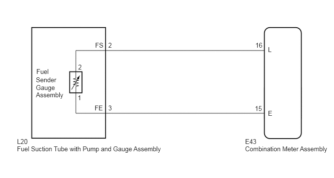
CAUTION / NOTICE / HINT
- HINT:
-
The fuel level warning light will come on when the fuel level is below 8.25 liters (8.7 US qts, 7.3 Imp. qts).
PROCEDURE
Ask the customer about the problem symptoms.
- Result:
Result Proceed to Malfunction occurs when adding fuel (Even after adding fuel, reading does not increase at all or increases very slowly, etc.) A Malfunction occurs during normal driving (The reading does not change, decreases quickly or decreases when the vehicle is not being driven, etc.) (The problem symptom recurs) B Malfunction occurs during normal driving (The reading does not change, decreases quickly or decreases when the vehicle is not being driven, etc.) (The problem symptom does not recur) C
A
B
C
Connect the GTS to the DLC3.
Turn the ignition switch to ON.
Turn the GTS on.
Enter following menus: Body Electrical / Combination Meter / Active Test.
Perform the Active Test according to the display on the GTS.
- Body Electrical > Combination Meter > Active Test
-
Tester Display Measurement Item Control Range Diagnostic Note Fuel Meter Operation Fuel receiver gauge OFF, Sender E, Empty, Warning, 1/4, 1/2, 3/4, Full or Sender F -
- Body Electrical > Combination Meter > Active Test
-
Tester Display Fuel Meter Operation - 50004 122 3
- OK:
Fuel receiver gauge indication is normal.
- Result:
Proceed to OK NG
OK
NG
Check if SFI system DTCs are output.
for 1ZR-FE: Click hereEngine / Hybrid System>1ZR-FE ENGINE CONTROL>SFI SYSTEM>DTC CHECK / CLEAR
for 2ZR-FE: Click hereEngine / Hybrid System>2ZR-FE ENGINE CONTROL>SFI SYSTEM>DTC CHECK / CLEAR
for 2NZ-FE: Click hereEngine / Hybrid System>2NZ-FE ENGINE CONTROL>SFI SYSTEM>DTC CHECK / CLEAR
- Powertrain > Engine and ECT > Trouble Codes
- 50001 234
- Result:
Result Proceed to DTCs are not output (w/ ABS) A DTCs are not output (w/o ABS) B DTCs are output C
A
B
C
for 1ZR-FE: Click hereEngine / Hybrid System>1ZR-FE ENGINE CONTROL>SFI SYSTEM>HOW TO PROCEED WITH TROUBLESHOOTING
for 2ZR-FE: Click hereEngine / Hybrid System>2ZR-FE ENGINE CONTROL>SFI SYSTEM>HOW TO PROCEED WITH TROUBLESHOOTING
for 2NZ-FE: Click hereEngine / Hybrid System>2NZ-FE ENGINE CONTROL>SFI SYSTEM>HOW TO PROCEED WITH TROUBLESHOOTING
Check if anti-lock brake system (w/ ABS) or vehicle stability control system (w/ VSC) DTCs are output.
w/ ABS: Click hereBrake>BRAKE CONTROL / DYNAMIC CONTROL SYSTEMS>ANTI-LOCK BRAKE SYSTEM>DTC CHECK / CLEAR
w/ VSC: Click hereBrake>BRAKE CONTROL / DYNAMIC CONTROL SYSTEMS>VEHICLE STABILITY CONTROL SYSTEM>DTC CHECK / CLEAR
- Chassis > ABS/VSC/TRC > Trouble Codes
- 50001 105
- Result:
Result Proceed to DTCs are not output A DTCs are output (w/ ABS) B DTCs are output (w/ VSC) C
A
B
C
Record the fuel receiver gauge reading.
If the fuel tank sub-assembly is almost full, drain 20 liters or more of fuel. (This is not necessary when the fuel tank sub-assembly is sufficiently below full.)
Disconnect the cable from the negative (-) battery terminal to reset the fuel receiver gauge.
- HINT:
-
Check that the ignition switch is turned off before disconnecting the cable from the negative (-) battery terminal.
Connect the cable to the negative (-) battery terminal and turn the ignition switch ON.
Check that the fuel receiver gauge has been reset.
Drive the vehicle at 1.75 km/h or more, then move the shift lever to P and turn the ignition switch off.
Add 5.0 liters or more of fuel, turn the ignition switch ON, and check that the fuel receiver gauge reading increases in proportion to the amount of fuel added.
- Result:
Result Proceed to Fuel receiver gauge reading increases in proportion to the amount of fuel added A Fuel receiver gauge reading does not change even when fuel is added B
A
B
- HINT:
-
Inspect the fuel tank sub-assembly for deformation, foreign matter or an improperly installed fuel receiver gauge, as this may be the cause of the fuel receiver gauge malfunction.
Visually check the fuel tank sub-assembly for any abnormalities.
Check if there is an excessive amount of foreign matter in the fuel tank sub-assembly.
Check the installation condition of the fuel tank sub-assembly and fuel sender gauge assembly.
- Result:
Result Proceed to Normal A Appearance of the fuel tank sub-assembly is abnormal B There is an excessive amount of foreign matter in the fuel tank sub-assembly C The fuel tank sub-assembly or fuel sender gauge assembly is not installed correctly D
A
B
for 1ZR-FE: Click hereEngine / Hybrid System>1ZR-FE FUEL>FUEL TANK>REMOVAL
for 2ZR-FE: Click hereEngine / Hybrid System>2ZR-FE FUEL>FUEL TANK>REMOVAL
for 2NZ-FE: Click hereEngine / Hybrid System>2NZ-FE FUEL>FUEL TANK>REMOVAL
C
D
Connect the GTS to the DLC3.
Turn the ignition switch to ON.
Turn the GTS on.
Enter following menus: Body Electrical / Combination Meter / Active Test.
Perform the Active Test according to the display on the GTS.
- Body Electrical > Combination Meter > Active Test
-
Tester Display Measurement Item Control Range Diagnostic Note Fuel Meter Operation Fuel receiver gauge OFF, Sender E, Empty, Warning, 1/4, 1/2, 3/4, Full or Sender F -
- Body Electrical > Combination Meter > Active Test
-
Tester Display Fuel Meter Operation - 50004 122 3
- OK:
Fuel receiver gauge indication is normal.
- Result:
Proceed to OK NG
OK
NG
Check if SFI system DTCs are output.
for 1ZR-FE: Click hereEngine / Hybrid System>1ZR-FE ENGINE CONTROL>SFI SYSTEM>DTC CHECK / CLEAR
for 2ZR-FE: Click hereEngine / Hybrid System>2ZR-FE ENGINE CONTROL>SFI SYSTEM>DTC CHECK / CLEAR
for 2NZ-FE: Click hereEngine / Hybrid System>2NZ-FE ENGINE CONTROL>SFI SYSTEM>DTC CHECK / CLEAR
- Powertrain > Engine and ECT > Trouble Codes
- 50001 234
- Result:
Result Proceed to DTCs are not output (w/ ABS) A DTCs are not output (w/o ABS) B DTCs are output C
A
B
C
for 1ZR-FE: Click hereEngine / Hybrid System>1ZR-FE ENGINE CONTROL>SFI SYSTEM>HOW TO PROCEED WITH TROUBLESHOOTING
for 2ZR-FE: Click hereEngine / Hybrid System>2ZR-FE ENGINE CONTROL>SFI SYSTEM>HOW TO PROCEED WITH TROUBLESHOOTING
for 2NZ-FE: Click hereEngine / Hybrid System>2NZ-FE ENGINE CONTROL>SFI SYSTEM>HOW TO PROCEED WITH TROUBLESHOOTING
Check if anti-lock brake system (w/ ABS) or vehicle stability control system (w/ VSC) DTCs are output.
w/ ABS: Click hereBrake>BRAKE CONTROL / DYNAMIC CONTROL SYSTEMS>ANTI-LOCK BRAKE SYSTEM>DTC CHECK / CLEAR
w/ VSC: Click hereBrake>BRAKE CONTROL / DYNAMIC CONTROL SYSTEMS>VEHICLE STABILITY CONTROL SYSTEM>DTC CHECK / CLEAR
- Chassis > ABS/VSC/TRC > Trouble Codes
- 50001 105
- Result:
Result Proceed to DTCs are not output A DTCs are output (w/ ABS) B DTCs are output (w/ VSC) C
A
B
C
Check if meter / gauge system DTCs are output.
Click hereVehicle Interior>METER / GAUGE / DISPLAY>METER / GAUGE SYSTEM>DTC CHECK / CLEAR
- Body Electrical > Combination Meter > Trouble Codes
- 50001 122
- Result:
Result Proceed to DTC B1500 is not output A DTC B1500 is output B
A
B
Disconnect the cable from the negative (-) battery terminal to reset the fuel receiver gauge.
- HINT:
-
Check that the ignition switch is turned off before disconnecting the cable from the negative (-) battery terminal.
Connect the cable to the negative (-) battery terminal and turn the ignition switch ON.
Check if the fuel receiver gauge reading corresponds with the amount of fuel remaining in the fuel tank sub-assembly.
- Result:
Result Proceed to Fuel receiver gauge reading corresponds with the amount of fuel remaining in the fuel tank sub-assembly A Fuel receiver gauge reading does not correspond with the amount of fuel remaining in the fuel tank sub-assembly B
A
B
Connect the GTS to the DLC3.
Turn the ignition switch to ON.
Turn the GTS on.
Enter following menus: Body Electrical / Combination Meter / Data List.
Read the Data List according to the display on the GTS.
- Body Electrical > Combination Meter > Data List
-
Tester Display Measurement Item Range Normal Condition Diagnostic Note Fuel Input Fuel input Min.: 0 L, Max.: 127.5 L Fuel receiver gauge indicates F: 49.5 L
Fuel receiver gauge indicates 3/4: 40.8 L
Fuel receiver gauge indicates 1/2: 27.5 L
Fuel receiver gauge indicates 1/4: 14.2 L
Fuel receiver gauge indicates E: 5.5 LUnit: Liter
- Body Electrical > Combination Meter > Data List
-
Tester Display Fuel Input - 50003 122 39
- Result:
Result Proceed to Fuel level data displayed on the GTS is almost the same as the fuel receiver gauge indication A Fuel level data displayed on the GTS differs from the fuel receiver gauge indication B
A
B
Disconnect the L20 fuel suction tube with pump and gauge assembly connector.
Disconnect the E43 combination meter assembly connector.
Measure the resistance according to the value(s) in the table below.
- Standard Resistance:
Tester Connection Condition Specified Condition L20-2 (FS) - E43-16 (L) Always Below 1 Ω L20-3 (FE) - E43-15 (E) Always Below 1 Ω L20-2 (FS) or E43-16 (L) - Body ground Always 10 kΩ or higher L20-3 (FE) or E43-15 (E) - Body ground Always 10 kΩ or higher
- Result:
Proceed to OK NG
OK
NG
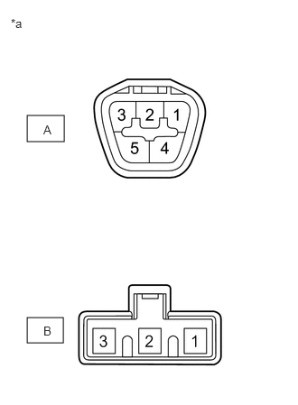
| *a | Component without harness connected
(Fuel Suction Tube with Pump and Gauge Assembly) |
Measure the resistance according to the value(s) in the table below.
- Standard Resistance:
Tester Connection Condition Specified Condition A-2 - B-2 Always Below 1 Ω A-3 - B-1 Always Below 1 Ω
- Result:
Proceed to OK NG
OK
NG
for 1ZR-FE: Click hereEngine / Hybrid System>1ZR-FE FUEL>FUEL SENDER GAUGE ASSEMBLY>REMOVAL
for 2ZR-FE: Click hereEngine / Hybrid System>2ZR-FE FUEL>FUEL SENDER GAUGE ASSEMBLY>REMOVAL
for 2NZ-FE: Click hereEngine / Hybrid System>2NZ-FE FUEL>FUEL SENDER GAUGE ASSEMBLY>REMOVAL
Remove the fuel sender gauge assembly.
for 1ZR-FE: Click hereEngine / Hybrid System>1ZR-FE FUEL>FUEL SENDER GAUGE ASSEMBLY>REMOVAL
for 2ZR-FE: Click hereEngine / Hybrid System>2ZR-FE FUEL>FUEL SENDER GAUGE ASSEMBLY>REMOVAL
for 2NZ-FE: Click hereEngine / Hybrid System>2NZ-FE FUEL>FUEL SENDER GAUGE ASSEMBLY>REMOVAL
Inspect the fuel sender gauge assembly.
for 1ZR-FE: Click hereEngine / Hybrid System>1ZR-FE FUEL>FUEL SENDER GAUGE ASSEMBLY>INSPECTION
for 2ZR-FE: Click hereEngine / Hybrid System>2ZR-FE FUEL>FUEL SENDER GAUGE ASSEMBLY>INSPECTION
for 2NZ-FE: Click hereEngine / Hybrid System>2NZ-FE FUEL>FUEL SENDER GAUGE ASSEMBLY>INSPECTION
- OK:
Fuel sender gauge assembly is normal.
- Result:
Proceed to OK NG
OK
NG
for 1ZR-FE: Click hereEngine / Hybrid System>1ZR-FE FUEL>FUEL SENDER GAUGE ASSEMBLY>REMOVAL
for 2ZR-FE: Click hereEngine / Hybrid System>2ZR-FE FUEL>FUEL SENDER GAUGE ASSEMBLY>REMOVAL
for 2NZ-FE: Click hereEngine / Hybrid System>2NZ-FE FUEL>FUEL SENDER GAUGE ASSEMBLY>REMOVAL
Check if SFI system DTCs are output.
for 1ZR-FE: Click hereEngine / Hybrid System>1ZR-FE ENGINE CONTROL>SFI SYSTEM>DTC CHECK / CLEAR
for 2ZR-FE: Click hereEngine / Hybrid System>2ZR-FE ENGINE CONTROL>SFI SYSTEM>DTC CHECK / CLEAR
for 2NZ-FE: Click hereEngine / Hybrid System>2NZ-FE ENGINE CONTROL>SFI SYSTEM>DTC CHECK / CLEAR
- Powertrain > Engine and ECT > Trouble Codes
- 50001 234
- Result:
Result Proceed to DTCs are not output (w/ ABS) A DTCs are not output (w/o ABS) B DTCs are output C
A
B
C
for 1ZR-FE: Click hereEngine / Hybrid System>1ZR-FE ENGINE CONTROL>SFI SYSTEM>HOW TO PROCEED WITH TROUBLESHOOTING
for 2ZR-FE: Click hereEngine / Hybrid System>2ZR-FE ENGINE CONTROL>SFI SYSTEM>HOW TO PROCEED WITH TROUBLESHOOTING
for 2NZ-FE: Click hereEngine / Hybrid System>2NZ-FE ENGINE CONTROL>SFI SYSTEM>HOW TO PROCEED WITH TROUBLESHOOTING
Check if anti-lock brake system (w/ ABS) or vehicle stability control system (w/ VSC) DTCs are output.
w/ ABS: Click hereBrake>BRAKE CONTROL / DYNAMIC CONTROL SYSTEMS>ANTI-LOCK BRAKE SYSTEM>DTC CHECK / CLEAR
w/ VSC: Click hereBrake>BRAKE CONTROL / DYNAMIC CONTROL SYSTEMS>VEHICLE STABILITY CONTROL SYSTEM>DTC CHECK / CLEAR
- Chassis > ABS/VSC/TRC > Trouble Codes
- 50001 105
- Result:
Result Proceed to DTCs are not output A DTCs are output (w/ ABS) B DTCs are output (w/ VSC) C
A
B
C
- HINT:
-
Inspect the fuel tank sub-assembly for deformation, foreign matter or an improperly installed fuel receiver gauge, as this may be the cause of the fuel receiver gauge malfunction.
Visually check the fuel tank sub-assembly for any abnormalities.
Check if there is an excessive amount of foreign matter in the fuel tank sub-assembly.
Check the installation condition of the fuel tank sub-assembly and fuel sender gauge assembly.
- Result:
Result Proceed to Normal A Appearance of the fuel tank sub-assembly is abnormal B There is an excessive amount of foreign matter in the fuel tank sub-assembly C The fuel tank sub-assembly or fuel sender gauge assembly is not installed correctly D
A
B
for 1ZR-FE: Click hereEngine / Hybrid System>1ZR-FE FUEL>FUEL TANK>REMOVAL
for 2ZR-FE: Click hereEngine / Hybrid System>2ZR-FE FUEL>FUEL TANK>REMOVAL
for 2NZ-FE: Click hereEngine / Hybrid System>2NZ-FE FUEL>FUEL TANK>REMOVAL
C
D