2NZ-FE FUEL FUEL SENDER GAUGE ASSEMBLY INSPECTION
PROCEDURE

 83320
1.INSPECT FUEL SENDER GAUGE ASSEMBLY
83320
1.INSPECT FUEL SENDER GAUGE ASSEMBLY
a.
Check that the float moves smoothly between F and E.
b.
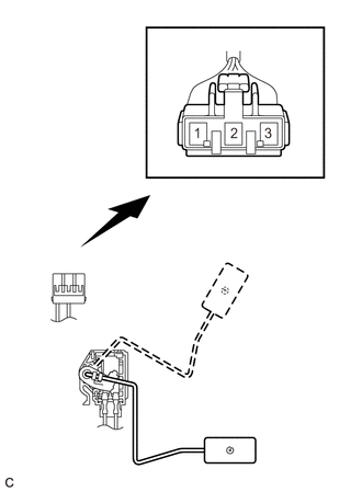
2.146,2.75 2.771,2.75
false
2.188,4.281 2.813,4.281
false
1.5,0.323 1.813,0.479
0.313,0.156
10
false
*a
2.865,2.667 3.021,2.865
0.156,0.198
10
false
F
2.896,4.198 3.052,4.396
0.156,0.198
10
false
E
| *a | Component without harness connected
(Fuel Sender Gauge Assembly) |
Inspect the fuel sender gauge assembly resistance.
i.
Measure the resistance according to the value(s) in the table below.
- Standard Resistance:
Tester Connection Float Level Specified Condition 1 - 2 F 13.5 to 16.5 Ω Between F and E 13.5 to 414.5 Ω (Gradually changes) E 405.5 to 414.5 Ω
If the result is not as specified, replace the fuel sender gauge assembly.