POWER ASSIST SYSTEMS POWER STEERING SYSTEM C1541 Vehicle Speed Signal Malfunction C1542 Vehicle Speed Signal Malfunction C1571 Speed Sensor Malfunction (Test Mode DTC)
DESCRIPTION
Based on the vehicle speed signal received from the combination meter assembly, the power steering ECU assembly adjusts the amount of power assist according to vehicle speed. The power steering ECU assembly monitors the speed signal input and stores a DTC if a malfunction is detected. While a malfunction exists in the vehicle speed signal, fail-safe operation maintains the amount of power assist at the level for a speed of 70 km/h (43 mph).
- NOTICE:
-
Revving the engine while the vehicle is stopped may cause DTC C1541 or C1542 to be stored.
- HINT:
- ·
If C1541 is stored while the vehicle is stopped, driving the vehicle for 5 minutes or more and then turning the ignition switch to off will clear the DTC.
·If C1542 is stored while the vehicle is stopped, driving the vehicle for 5 minutes or more will clear the DTC.
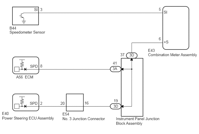
·A voltage of 12 V or 5 V is output from each ECU and then input to the combination meter assembly. The signal is changed to a pulse signal at the transistor in the combination meter assembly. Each ECU controls the respective system based on the pulse signal.
·If a short occurs in any of the ECUs or in the wire harness connected to an ECU, all systems in the diagram below will not operate normally.
| DTC No. | Detection Item | DTC Detection Condition | Trouble Area | Warning Indicate | Return-to-normal Condition | Note |
|---|---|---|---|---|---|---|
| C1541 | Vehicle Speed Signal Malfunction | ·
Vehicle Speed Signal Abnormal Increase ·
While vehicle stopped, engine rpm exceeds threshold (Threshold: An engine speed of 4000 rpm or greater is detected within 5 minutes after engine is started, or an engine speed of 2100 rpm or greater is detected 5 minutes or more after engine is started.) for 300 seconds or more, cumulative. |
·
Open or short in speed signal circuit ·
Combination meter assembly ·
ECM ·
Power steering ECU assembly ·
Speed sensor |
EPS warning light: Comes on | After normal confirmation | w/o ABS |
| C1542 | Vehicle Speed Signal Malfunction | ·
Vehicle Speed Signal Abnormal Decrease ·
While vehicle stopped, engine rpm exceeds threshold (Threshold: An engine speed of 4000 rpm or greater is detected within 5 minutes after engine is started, or an engine speed of 2100 rpm or greater is detected 5 minutes or more after engine is started.) for 30 seconds or more, cumulative. |
·
Open or short in speed signal circuit ·
Combination meter assembly ·
ECM ·
Power steering ECU assembly ·
Speed sensor |
EPS warning light: Comes on | After normal confirmation | w/o ABS |
| C1571 | Speed Sensor Malfunction (Test Mode DTC) | Speed sensor malfunction (Test mode). | If the code cannot be cleared, any of the following areas may be malfunctioning:
·
Speed sensor ·
Combination meter assembly ·
Power steering ECU assembly ·
Wire harness and connector |
EPS warning light: Does not come on | - | w/o ABS |
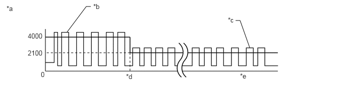
| *a | Engine Speed (rpm) | *b | 30 seconds cumulative C1542 stored |
| *c | 300 seconds cumulative C1541 stored | *d | 5 minutes |
| *e | Elapsed time after engine start | - | - |
WIRING DIAGRAM
CAUTION / NOTICE / HINT
- NOTICE:
-
If the power steering ECU assembly has been replaced, perform assist map writing and torque sensor zero point calibration.
-
Click hereSteering>POWER ASSIST SYSTEMS>POWER STEERING SYSTEM>CALIBRATION
PROCEDURE
Perform signal check in the Test Mode procedure.
Click hereSteering>POWER ASSIST SYSTEMS>POWER STEERING SYSTEM>TEST MODE PROCEDURE
- Chassis > EMPS > Utility
-
Tester Display Signal Check - 50005 142 3
- OK:
Test mode DTC C1571 is cleared.
- Result:
Proceed to OK NG
OK
NG
The circuits that sent vehicle speed signals to this system are inspected in the meter system.
Click hereVehicle Interior>METER / GAUGE / DISPLAY>METER / GAUGE SYSTEM>Speedometer Malfunction
During inspection for the meter section, if there is an instruction that indicates to go back to inspection for each system, proceed to the next step.
- Result:
Proceed to NEXT
NEXT
Disconnect the E43 combination meter assembly connector.
Disconnect the E40 power steering ECU assembly connector.
Measure the resistance according to the value(s) in the table below.
- Standard Resistance:
Tester Connection Condition Specified Condition E40-2 (SPD) - E43-6 (+S) Always Below 1 Ω E40-2 (SPD) or E43-6 (+S) - Body ground Always 10 kΩ or higher
- Result:
Proceed to OK NG
OK
NG
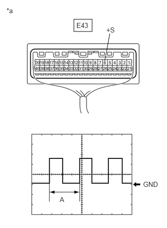
| *a | Component with harness connected
(Combination Meter Assembly) |
Check the input waveform.
Remove the combination meter assembly with the connector(s) still connected.
Connect an oscilloscope to terminal E43-6 (+S) and body ground.
Turn the ignition switch to ON.
Turn a wheel slowly.
Check the signal waveform according to the condition(s) in the table below.
| Item | Condition |
|---|---|
| Tool setting | 5 V/DIV., 20 ms./DIV. |
| Vehicle condition | Driving at approx. 20 km/h (12 mph) |
- OK:
The waveform is similar to that shown in the illustration.
- HINT:
-
When the system is functioning normally, one wheel revolution generates 4 pulses. As the vehicle speed increases, the width indicated by (A) in the illustration narrows.
- Result:
Proceed to OK NG
OK
NG