METER / GAUGE / DISPLAY COMBINATION METER REMOVAL
PROCEDURE

 1. PRECAUTION
- NOTICE:
-
After turning the ignition switch off, waiting time may be required before disconnecting the cable from the negative (-) battery terminal. Therefore, make sure to read the disconnecting the cable from the negative (-) battery terminal notices before proceeding with work.
-
Click hereGeneral>INTRODUCTION>REPAIR INSTRUCTION>PRECAUTION
2.DISCONNECT CABLE FROM NEGATIVE BATTERY TERMINAL
- NOTICE:
-
When disconnecting the cable, some systems need to be initialized after the cable is reconnected.
-
Click hereGeneral>INTRODUCTION>REPAIR INSTRUCTION>INITIALIZATION
55012A
3.REMOVE NO. 2 INSTRUMENT PANEL GARNISH SUB-ASSEMBLY
55650
4.REMOVE NO. 1 INSTRUMENT PANEL REGISTER ASSEMBLY
55011A
5.REMOVE NO. 1 INSTRUMENT PANEL GARNISH SUB-ASSEMBLY
55405B
6.REMOVE CENTER INSTRUMENT CLUSTER FINISH PANEL SUB-ASSEMBLY
55410C
7.REMOVE INSTRUMENT CLUSTER FINISH PANEL ASSEMBLY
83100
8.REMOVE COMBINATION METER ASSEMBLY
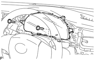
Remove the 2 screws.
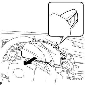
Disengage the 2 clips as shown in the illustration.
Disconnect each connector and remove the combination meter assembly.