2ZR-FE ENGINE CONTROL  SFI SYSTEM  VC Output Circuit  


DESCRIPTION

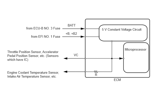
The ECM constantly generates a 5 V power source voltage from the battery voltage supplied to the +B, +B2 (BATT) terminal to operate the microprocessor. The ECM also provides this power source voltage to the sensors through the VC output circuit.
A206916E40
4.375,1.177 6.198,1.354 1.823,0.177 10 false 5 V Constant Voltage Circuit 5.354,2.031 6.365,2.188 1.01,0.156 10 false Microprocessor 1.125,1.125 2.677,1.354 1.552,0.229 10 false from ECU-B NO. 3 Fuse 1.333,1.479 2.729,1.667 1.396,0.188 10 false from EFI NO. 1 Fuse 2.906,1 3.427,1.219 0.521,0.219 10 false BATT 0.313,2.135 2.635,2.677 2.323,0.542 10 false Throttle Position Sensor, Accelerator Pedal Position Sensor, etc. (Sensors which have IC) 0.313,3.021 2.677,3.448 2.365,0.427 10 false Engine Coolant Temperature Sensor, Intake Air Temperature Sensor, etc. 4.073,3.115 4.333,3.323 0.26,0.208 10 false R 2.813,1.354 3.375,1.552 0.563,0.198 10 false +B, +B2 3.167,2.271 3.458,2.5 0.292,0.229 10 false VC 4.885,3.333 5.229,3.51 0.344,0.177 10 false ECM

When the VC circuit is short-circuited, the microprocessor in the ECM and the sensors that are supplied with power through the VC circuit are inactivated because power is not supplied from the VC circuit. Under this condition, the system does not start up and the MIL does not illuminate even if the system malfunctions.

HINT:

Under normal conditions, the MIL is illuminated when the ignition switch is turned to ON. The MIL goes off when the engine is started.


WIRING DIAGRAM
A311273E12
1.979,0.865 2.292,1.063 0.313,0.198 10 false VC 1.99,1.25 2.302,1.448 0.313,0.198 10 false E2 1.896,1.594 2.208,1.792 0.313,0.198 10 false VTA 1.823,1.948 2.448,2.333 0.625,0.385 10 false VTA2 5.354,1.969 5.979,2.354 0.625,0.385 10 false VTA2 5.354,1.604 5.979,1.99 0.625,0.385 10 false VTA1 5.344,1.125 5.969,1.51 0.625,0.385 10 false ETA 5.344,0.75 5.854,1.021 0.51,0.271 10 false VCTA 6.344,0.552 6.656,0.854 0.313,0.302 10 false 5 V 4.99,0.854 5.323,1.063 0.333,0.208 10 false B33 4.99,1.219 5.323,1.427 0.333,0.208 10 false B33 4.99,1.583 5.323,1.792 0.333,0.208 10 false B33 5,1.958 5.333,2.167 0.333,0.208 10 false B33 4.99,2.458 5.323,2.667 0.333,0.208 10 false A40 4.99,2.813 5.323,3.021 0.333,0.208 10 false A40 4.99,3.188 5.323,3.396 0.333,0.208 10 false A40 4.99,3.542 5.323,3.75 0.333,0.208 10 false A40 4.99,3.917 5.323,4.125 0.333,0.208 10 false A40 4.99,4.281 5.323,4.49 0.333,0.208 10 false A40 4.99,4.906 5.323,5.115 0.333,0.208 10 false B33 4.99,5.271 5.323,5.479 0.333,0.208 10 false B33 4.99,5.635 5.323,5.844 0.333,0.208 10 false B33 5,6.375 5.333,6.583 0.333,0.208 10 false B33 5,6.729 5.333,6.938 0.333,0.208 10 false B33 4.99,7.094 5.323,7.302 0.333,0.208 10 false B33 4.99,7.865 5.323,8.073 0.333,0.208 10 false B33 4.99,8.25 5.323,8.458 0.333,0.208 10 false B33 4.99,8.635 5.323,8.844 0.333,0.208 10 false B33 1.781,2.469 2.292,2.74 0.51,0.271 10 false VCPA 1.802,2.823 2.313,3.094 0.51,0.271 10 false VCP2 1.865,3.198 2.375,3.469 0.51,0.271 10 false VPA 1.802,3.563 2.313,3.833 0.51,0.271 10 false VPA2 1.865,3.906 2.375,4.177 0.51,0.271 10 false EPA 1.792,4.271 2.302,4.542 0.51,0.271 10 false EPA2 0.542,0.875 1,1.073 0.458,0.198 10 false B24 0.542,1.052 1.427,1.458 0.885,0.406 10 false Throttle Body Assembly 0.531,2.563 0.99,2.76 0.458,0.198 10 false A2 0.531,2.729 1.677,3.167 1.146,0.438 10 false Accelerator Pedal Sensor Assembly 0.531,4.76 0.99,4.958 0.458,0.198 10 false B21 0.531,4.938 1.698,5.51 1.167,0.573 10 false Camshaft Position Sensor (for Intake Camshaft) 1.958,4.906 2.271,5.104 0.313,0.198 10 false VC 1.833,6.729 2.344,6.979 0.51,0.25 10 false VVE- 1.875,5.646 2.323,5.927 0.448,0.281 10 false VVI+ 0.531,6.271 0.99,6.469 0.458,0.198 10 false B20 0.531,6.448 1.719,7.01 1.188,0.563 10 false Camshaft Position Sensor (for Exhaust Camshaft) 1.885,6.365 2.198,6.563 0.313,0.198 10 false VC2 1.823,7.094 2.333,7.344 0.51,0.25 10 false VVE+ 0.531,7.76 0.99,7.958 0.458,0.198 10 false B29 0.521,7.927 1.865,8.271 1.344,0.344 10 false Oil Pressure Sensor* 1.885,5.26 2.333,5.542 0.448,0.281 10 false VVI- 1.958,7.865 2.271,8.063 0.313,0.198 10 false VC 1.979,8.25 2.292,8.448 0.313,0.198 10 false E2 1.885,8.635 2.198,8.833 0.313,0.198 10 false PTO 0.448,9.167 1.604,9.427 1.156,0.26 10 false *: for CVT Models 5.802,9.219 6.26,9.417 0.458,0.198 10 false ECM 2.313,7.75 2.469,7.948 0.156,0.198 10 false 3 2.302,8.135 2.458,8.333 0.156,0.198 10 false 1 2.313,8.51 2.469,8.708 0.156,0.198 10 false 2 3.531,7.781 3.688,7.979 0.156,0.198 10 false * 3.531,8.188 3.688,8.385 0.156,0.198 10 false * 3.531,8.552 3.688,8.75 0.156,0.198 10 false * 2.313,6.24 2.469,6.438 0.156,0.198 10 false 3 2.313,6.625 2.469,6.823 0.156,0.198 10 false 2 2.302,6.99 2.458,7.188 0.156,0.198 10 false 1 2.313,5.146 2.469,5.344 0.156,0.198 10 false 2 2.313,5.51 2.469,5.708 0.156,0.198 10 false 1 2.313,4.792 2.469,4.99 0.156,0.198 10 false 3 2.313,4.156 2.469,4.354 0.156,0.198 10 false 2 2.313,3.802 2.469,4 0.156,0.198 10 false 5 2.313,3.438 2.469,3.635 0.156,0.198 10 false 3 2.313,3.073 2.469,3.271 0.156,0.198 10 false 6 2.313,2.729 2.469,2.927 0.156,0.198 10 false 1 2.313,2.344 2.469,2.542 0.156,0.198 10 false 4 2.313,0.75 2.469,0.948 0.156,0.198 10 false 5 2.313,1.094 2.469,1.292 0.156,0.198 10 false 3 2.313,1.479 2.469,1.677 0.156,0.198 10 false 6 2.313,1.844 2.469,2.042 0.156,0.198 10 false 4 5.354,2.354 5.865,2.625 0.51,0.271 10 false VCPA 5.354,2.719 5.865,2.99 0.51,0.271 10 false VCP2 5.365,3.208 5.875,3.479 0.51,0.271 10 false VPA 5.354,3.813 5.865,4.083 0.51,0.271 10 false EPA 5.354,3.552 5.865,3.823 0.51,0.271 10 false VPA2 5.354,4.156 5.865,4.427 0.51,0.271 10 false EPA2 5.354,4.802 5.875,5.083 0.521,0.281 10 false VCV1 5.354,5.156 5.802,5.438 0.448,0.281 10 false VV1- 5.354,5.656 5.802,5.938 0.448,0.281 10 false VV1+ 5.354,6.271 5.781,6.51 0.427,0.24 10 false VCE1 5.354,6.615 5.781,6.854 0.427,0.24 10 false EV1- 5.354,7.104 5.781,7.344 0.427,0.24 10 false EV1+ 5.354,7.75 5.927,8.042 0.573,0.292 10 false VCPT* 5.354,8.146 5.958,8.448 0.604,0.302 10 false EPTO* 5.354,8.656 5.792,8.896 0.438,0.24 10 false PTO* 4.99,0.688 5.448,0.885 0.458,0.198 10 false 115 4.99,1.052 5.448,1.25 0.458,0.198 10 false 116 5.042,1.417 5.5,1.615 0.458,0.198 10 false 84 5.042,1.781 5.5,1.979 0.458,0.198 10 false 83 5.042,2.281 5.5,2.479 0.458,0.198 10 false 53 5.031,2.656 5.49,2.854 0.458,0.198 10 false 56 5.042,3.01 5.5,3.208 0.458,0.198 10 false 51 5.042,3.375 5.5,3.573 0.458,0.198 10 false 54 5.042,3.74 5.5,3.938 0.458,0.198 10 false 52 5.031,4.115 5.49,4.313 0.458,0.198 10 false 55 5,4.729 5.458,4.927 0.458,0.198 10 false 113 5,5.094 5.458,5.292 0.458,0.198 10 false 114 5.031,5.469 5.49,5.667 0.458,0.198 10 false 82 5,6.198 5.458,6.396 0.458,0.198 10 false 111 5,6.563 5.458,6.76 0.458,0.198 10 false 112 5.042,6.927 5.5,7.125 0.458,0.198 10 false 80 4.99,7.688 5.448,7.885 0.458,0.198 10 false 120 4.99,8.073 5.448,8.271 0.458,0.198 10 false 121 5.031,8.448 5.49,8.646 0.458,0.198 10 false 89

PROCEDURE

1.CHECK MIL CONDITION
a.

Check that the Malfunction Indicator Lamp (MIL) illuminates when the ignition switch is turned to ON.

OK:

MIL illuminates.


Result:
Proceed to
OK
NG


OK

PROCEED TO NEXT SUSPECTED AREA SHOWN IN PROBLEM SYMPTOMS TABLE

NG

2.CHECK CONNECTION BETWEEN GTS AND ECM
a.

Connect the GTS to the DLC3.


b.

Turn the ignition switch to ON.


c.

Turn the GTS on.


d.

Check for communication between the GTS and ECM.


Result:
Result Proceed to
Communication is not possible A
Communication is possible B


A

3.CHECK MIL (THROTTLE POSITION SENSOR)

B

3.CHECK MIL (THROTTLE POSITION SENSOR)
a.

Disconnect the throttle body assembly connector.


b.

Turn the ignition switch to ON.


c.

Check the MIL.

Result:
Result Proceed to
MIL does not illuminate A
MIL illuminates B


HINT:

Perform "Inspection After Repair" after replacing the throttle body assembly.

Click hereEngine / Hybrid System>2ZR-FE ENGINE CONTROL>SFI SYSTEM>INITIALIZATION


A

4.CHECK MIL (ACCELERATOR PEDAL SENSOR ASSEMBLY)

B

4.CHECK MIL (ACCELERATOR PEDAL SENSOR ASSEMBLY)
a.

Disconnect the accelerator pedal sensor assembly connector.


b.

Turn the ignition switch to ON.


c.

Check the MIL.


Result:
Result Proceed to
MIL does not illuminate A
MIL illuminates B


A

5.CHECK MIL (CAMSHAFT POSITION SENSOR (FOR INTAKE CAMSHAFT))

B

REPLACE ACCELERATOR PEDAL SENSOR ASSEMBLY

5.CHECK MIL (CAMSHAFT POSITION SENSOR (FOR INTAKE CAMSHAFT))
a.

Disconnect the camshaft position sensor (for intake camshaft) connector.


b.

Turn the ignition switch to ON.


c.

Check the MIL.


Result:
Result Proceed to
MIL does not illuminate A
MIL illuminates B


A

6.CHECK MIL (CAMSHAFT POSITION SENSOR (FOR EXHAUST CAMSHAFT))

B

REPLACE CAM POSITION SENSOR (FOR INTAKE CAMSHAFT)

6.CHECK MIL (CAMSHAFT POSITION SENSOR (FOR EXHAUST CAMSHAFT))
a.

Disconnect the camshaft position sensor (for exhaust camshaft) connector.


b.

Turn the ignition switch to ON.


c.

Check the MIL.


Result:
Result Proceed to
MIL does not illuminate
(for CVT Models)
A
MIL does not illuminate
(for M/T Models)
B
MIL illuminates C


A

7.CHECK MIL (OIL PRESSURE SENSOR)

B

8.CHECK HARNESS AND CONNECTOR

C

REPLACE CAM POSITION SENSOR (FOR EXHAUST CAMSHAFT)

7.CHECK MIL (OIL PRESSURE SENSOR)
a.

Disconnect the oil pressure sensor connector.


b.

Turn the ignition switch to ON.


c.

Check the MIL.


Result:
Result Proceed to
MIL does not illuminate A
MIL illuminates B


A

8.CHECK HARNESS AND CONNECTOR

B

REPLACE OIL PRESSURE SENSOR

8.CHECK HARNESS AND CONNECTOR
a.

Disconnect the throttle body assembly connector.


b.

Disconnect the accelerator pedal sensor assembly connector.


c.

Disconnect the camshaft position sensor (for intake camshaft) connector.


d.

Disconnect the camshaft position sensor (for exhaust camshaft) connector.


e.

Disconnect the oil pressure sensor connector (for CVT Models).


f.

Disconnect the ECM connectors.


g.

Measure the resistance according to the value(s) in the table below.

Standard Resistance:
Tester Connection Condition Specified Condition
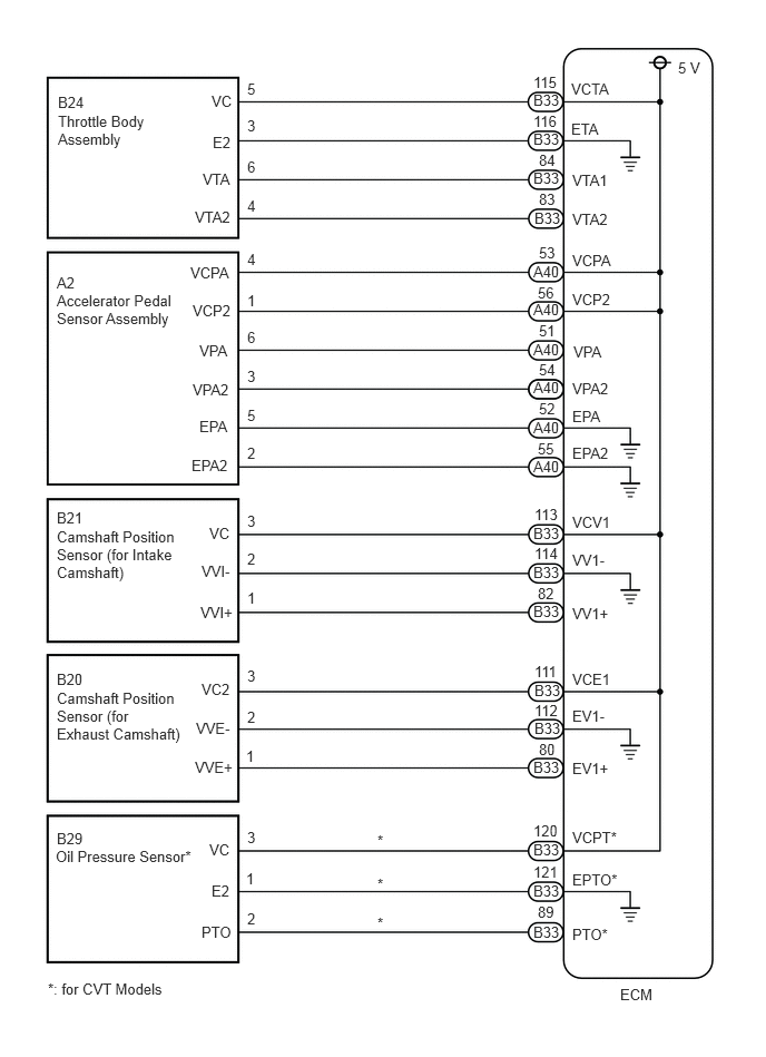
B33-115 (VCTA) - Body ground Always 10 kΩ or higher
A40-53 (VCPA) - Body ground Always 10 kΩ or higher
A40-56 (VCP2) - Body ground Always 10 kΩ or higher
B33-113 (VCV1) - Body ground Always 10 kΩ or higher
B33-111 (VCE1) - Body ground Always 10 kΩ or higher
B33-120 (VCPT)* - Body ground Always 10 kΩ or higher


*: for CVT Models


Result:
Proceed to
OK
NG


OK

NG

REPAIR OR REPLACE HARNESS OR CONNECTOR