2ZR-FE ENGINE MECHANICAL CYLINDER HEAD GASKET REMOVAL
PROCEDURE

 1.INSTALL ENGINE TO ENGINE STAND
2.REMOVE ENGINE HANGER
25719
3.REMOVE VACUUM SURGE TANK
17111
4.REMOVE INTAKE MANIFOLD
23901
5.DISCONNECT FUEL TUBE SUB-ASSEMBLY
23807
6.REMOVE FUEL DELIVERY PIPE SUB-ASSEMBLY
23807V
7.REMOVE NO. 1 DELIVERY PIPE SPACER
23250
8.REMOVE FUEL INJECTOR ASSEMBLY
11452
9.REMOVE ENGINE OIL LEVEL DIPSTICK GUIDE
17167
10.REMOVE NO. 1 EXHAUST MANIFOLD HEAT INSULATOR
12321B
11.REMOVE DRIVE SHAFT HEAT INSULATOR SUB-ASSEMBLY
17118
12.REMOVE MANIFOLD STAY
17141
13.REMOVE EXHAUST MANIFOLD
12261
14.REMOVE VENTILATION HOSE
16267
15.DISCONNECT NO. 3 WATER BY-PASS HOSE
16268
16.REMOVE NO. 1 WATER BY-PASS PIPE
16261
17.REMOVE NO. 1 WATER BY-PASS HOSE
16262
18.REMOVE WATER INLET HOSE
16321
19.REMOVE WATER INLET
16331A
20.REMOVE THERMOSTAT
19500
21.REMOVE IGNITION COIL ASSEMBLY
11201
22.REMOVE CYLINDER HEAD COVER SUB-ASSEMBLY
11213
23.REMOVE CYLINDER HEAD COVER GASKET
24.SET NO. 1 CYLINDER TO TDC/COMPRESSION
16620
25.REMOVE V-RIBBED BELT TENSIONER ASSEMBLY
13471
26.REMOVE CRANKSHAFT PULLEY
13540
27.REMOVE NO. 1 CHAIN TENSIONER ASSEMBLY
28.REMOVE TIMING CHAIN COVER SUB-ASSEMBLY
11302A
29.REMOVE TIMING CHAIN COVER OIL SEAL
13562
30.REMOVE NO. 2 CHAIN VIBRATION DAMPER
13559
31.REMOVE CHAIN TENSIONER SLIPPER
13561
32.REMOVE NO. 1 CHAIN VIBRATION DAMPER
13506
33.REMOVE CHAIN SUB-ASSEMBLY
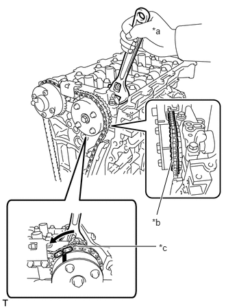
| *a | Turn |
| *b | Place the Chain Sub-assembly on the Camshaft Timing Gear Assembly |
| *c | Loosen the Chain Sub-assembly |
Hold the hexagonal portion of the camshaft with a wrench and turn the camshaft timing gear assembly counterclockwise to loosen the chain sub-assembly between the camshaft timing gear assembly and camshaft timing exhaust gear assembly.
With the chain sub-assembly loosened, release the chain sub-assembly from the camshaft timing gear assembly and place it on the camshaft timing gear assembly.
- HINT:
-
Be sure to release the chain sub-assembly from the sprocket completely.
Turn the camshaft clockwise to return it to the original position and remove the chain sub-assembly.
34.REMOVE CAMSHAFT BEARING CAP
13511
35.REMOVE CAMSHAFT
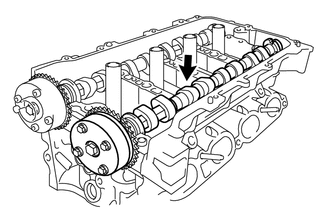
Remove the camshaft from the camshaft housing sub-assembly.
13512
36.REMOVE NO. 2 CAMSHAFT
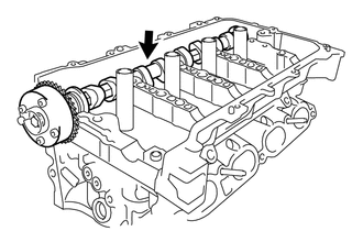
Remove the No. 2 camshaft from the camshaft housing sub-assembly.
11811
37.REMOVE NO. 1 CAMSHAFT BEARING
11821
38.REMOVE NO. 2 CAMSHAFT BEARING
13801
39.REMOVE NO. 1 VALVE ROCKER ARM SUB-ASSEMBLY
13750
40.REMOVE VALVE LASH ADJUSTER ASSEMBLY
11103
41.REMOVE CAMSHAFT HOUSING SUB-ASSEMBLY
11101
42.REMOVE CYLINDER HEAD SUB-ASSEMBLY
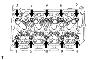
Using a 10 mm bi-hexagon wrench, uniformly loosen and remove the 10 cylinder head set bolts and 10 plate washers in several steps in the order shown in the illustration.
- NOTICE:
- ·
Removing the cylinder head set bolts in the wrong order may cause warpage or cracking of the cylinder head sub-assembly.
·Do not drop the plate washers into the cylinder head sub-assembly.
Using a screwdriver, remove the cylinder head sub-assembly by prying between the cylinder head sub-assembly and cylinder block sub-assembly, and remove the cylinder head sub-assembly.
- NOTICE:
-
Be careful not to damage the contact surfaces of the cylinder head sub-assembly and cylinder block sub-assembly.
- HINT:
-
Tape the screwdriver tip before use.
11115
43.REMOVE CYLINDER HEAD GASKET
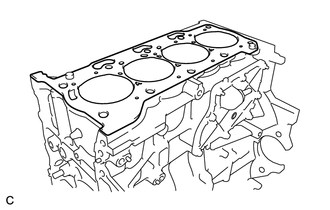
Remove the cylinder head gasket from the cylinder block sub-assembly.