2ZR-FE ENGINE MECHANICAL ENGINE UNIT REMOVAL
PROCEDURE

 25719
1.REMOVE VACUUM SURGE TANK
25719
1.REMOVE VACUUM SURGE TANK
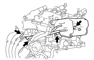
Disconnect the No. 2 air hose and No. 3 air hose.
Remove the 2 bolts and vacuum surge tank.
17111
2.REMOVE INTAKE MANIFOLD
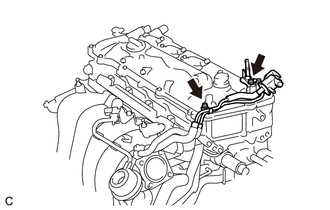
Remove the 2 bolts and disconnect the air tube from the cylinder head cover sub-assembly.
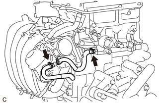
Slide the 2 clips and disconnect the No. 1 water by-pass hose and No. 2 water by-pass hose.
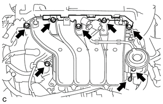
Slide the clip and disconnect the ventilation hose from the intake manifold.
Remove the 5 bolts, 2 nuts, intake manifold and intake manifold stay.
Remove the No. 1 intake manifold to head gasket from the intake manifold.
23901
3.DISCONNECT FUEL TUBE SUB-ASSEMBLY
23807
4.REMOVE FUEL DELIVERY PIPE SUB-ASSEMBLY
23807V
5.REMOVE NO. 1 DELIVERY PIPE SPACER
23250
6.REMOVE FUEL INJECTOR ASSEMBLY
11452
7.REMOVE ENGINE OIL LEVEL DIPSTICK GUIDE
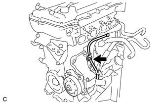
Remove the engine oil level dipstick.
Remove the bolt and engine oil level dipstick guide.
Remove the O-ring from the engine oil level dipstick guide.
17167
8.REMOVE NO. 1 EXHAUST MANIFOLD HEAT INSULATOR
12321B
9.REMOVE DRIVE SHAFT HEAT INSULATOR SUB-ASSEMBLY
17118
10.REMOVE MANIFOLD STAY
17141
11.REMOVE EXHAUST MANIFOLD
12261
12.REMOVE VENTILATION HOSE
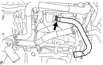
Slide the clip and remove the ventilation hose from the PCV valve (ventilation valve sub-assembly).
16267
13.DISCONNECT NO. 3 WATER BY-PASS HOSE
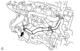
Slide the clip and disconnect the No. 3 water by-pass hose from the water inlet housing.
16268
14.REMOVE NO. 1 WATER BY-PASS PIPE
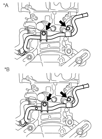
| *A | for Manual Transaxle |
| *B | for CVT |
Remove the 2 bolts and No. 1 water by-pass pipe.
16261
15.REMOVE NO. 1 WATER BY-PASS HOSE
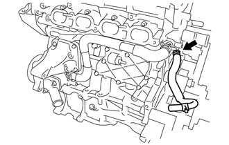
Slide the clip and remove the No. 1 water by-pass hose from the cylinder head sub-assembly.
16262
16.REMOVE WATER INLET HOSE
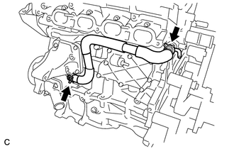
Slide the 2 clips and remove the water inlet hose.
16321
17.REMOVE WATER INLET
16331A
18.REMOVE THERMOSTAT
19500
19.REMOVE IGNITION COIL ASSEMBLY
16620
20.REMOVE V-RIBBED BELT TENSIONER ASSEMBLY
Rotate the V-ribbed belt tensioner assembly clockwise and remove the 5 mm hexagon wrench that was used to secure the V-ribbed belt tensioner assembly when removing the V-ribbed belt.
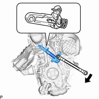
Rotate the V-ribbed belt tensioner assembly slightly clockwise and secure it using a 3 mm hexagon wrench as shown in the illustration.
- HINT:
-
It is difficult to install the V-ribbed belt tensioner assembly when it is fully extended. When reusing the V-ribbed belt tensioner assembly, compress and secure the V-ribbed belt tensioner assembly before removing it.
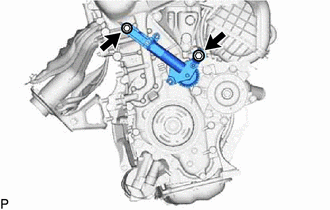
Remove the 2 bolts and V-ribbed belt tensioner assembly from the engine assembly.
89429F
21.REMOVE ENGINE OIL TEMPERATURE SENSOR