2ZR-FE FUEL FUEL INJECTOR REMOVAL
CAUTION / NOTICE / HINT
- HINT:
-
Perform "Inspection After Repair" after replacing a fuel injector assembly.
-
Click hereEngine / Hybrid System>2ZR-FE ENGINE CONTROL>SFI SYSTEM>INITIALIZATION
PROCEDURE

 1. PRECAUTION
- NOTICE:
-
After turning the ignition switch off, waiting time may be required before disconnecting the cable from the negative (-) battery terminal. Therefore, make sure to read the disconnecting the cable from the negative (-) battery terminal notices before proceeding with work.
-
Click hereGeneral>INTRODUCTION>REPAIR INSTRUCTION>PRECAUTION
2. DISCHARGE FUEL SYSTEM PRESSURE
3.DISCONNECT CABLE FROM NEGATIVE BATTERY TERMINAL
- NOTICE:
-
When disconnecting the cable, some systems need to be initialized after the cable is reconnected.
-
Click hereGeneral>INTRODUCTION>REPAIR INSTRUCTION>INITIALIZATION
11212
4.REMOVE NO. 2 CYLINDER HEAD COVER
17705
5.REMOVE AIR CLEANER CAP WITH AIR CLEANER HOSE
17701
6.REMOVE AIR CLEANER CASE SUB-ASSEMBLY
82121
7.DISCONNECT ENGINE WIRE
Disengage the 10 clamps, and then disconnect the 21 connectors.
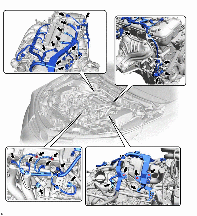
Remove the 3 bolts and 3 nuts, and disconnect the engine wire.
25719
8.REMOVE VACUUM SURGE TANK
23901
9.DISCONNECT FUEL TUBE SUB-ASSEMBLY
- NOTICE:
-
Remove any dirt or foreign matter on the fuel tube connector and fuel pipe before performing this work.
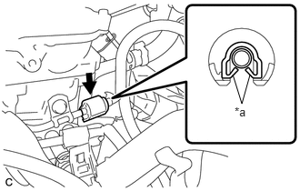
| *a | Claw |
Disengage the 2 claws to remove the No. 2 fuel pipe clamp.
- NOTICE:
-
Do not reuse the No. 2 fuel pipe clamp.
Disconnect the fuel tube sub-assembly from the fuel delivery pipe sub-assembly.
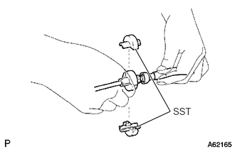
Install SST (fuel hose puller) to the fuel tube connector as shown in the illustration.
- SST
- 09268-21011
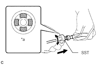
| *a | Retainer (4 places) |
Turn SST (fuel hose puller), align the retainers inside the fuel tube connector with the SST (fuel hose puller) chamfers and insert SST (fuel hose puller) into the fuel tube connector.
Mount the retainers of the fuel tube connector onto the chamfered part of SST (fuel hose puller).
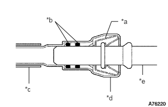
| *a | Retainer |
| *b | O-ring |
| *c | Nylon Tube |
| *d | Fuel Tube Connector |
| *e | Fuel Pipe |
Slide SST (fuel hose puller) and the fuel tube connector together until they make a "click" sound, and then disconnect the fuel tube connector.
- NOTICE:
- ·
Do not scratch or allow any foreign matter to get on the parts when disconnecting them as the fuel tube connector has O-rings that seal the pipe (fuel pipe).
·Do not bend, twist, pinch or kink the nylon tube.
Check that there is no foreign matter on the sealing surfaces of the disconnected fuel lines. Clean them if necessary.
Cover the disconnected fuel pipe and fuel tube connector with plastic bags to prevent damage and contamination.
89421
10.REMOVE VACUUM SENSOR (E.F.I. VACUUM SENSOR ASSEMBLY)
89426
11.REMOVE VACUUM SENSOR BRACKET
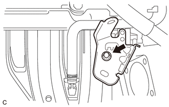
Remove the engine cover joint and vacuum sensor bracket from the intake manifold.
23807
12.REMOVE FUEL DELIVERY PIPE SUB-ASSEMBLY
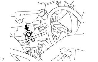
Remove the bolt to separate the clamp of the fuel delivery pipe sub-assembly from the cylinder head sub-assembly.
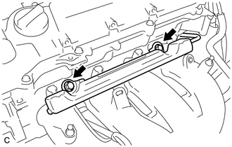
Remove the 2 bolts and fuel delivery pipe sub-assembly with the 4 fuel injector assemblies.
- NOTICE:
-
Do not drop the fuel injector assemblies when removing the fuel delivery pipe sub-assembly.
23807V
13.REMOVE NO. 1 DELIVERY PIPE SPACER
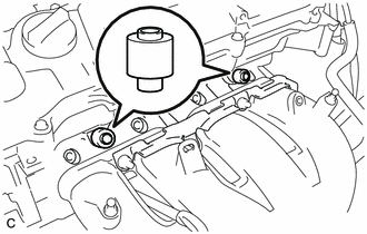
Remove the 2 No. 1 delivery pipe spacers from the cylinder head sub-assembly.
23250
14.REMOVE FUEL INJECTOR ASSEMBLY
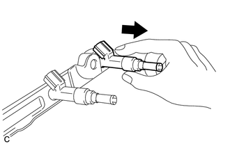
Pull the 4 fuel injector assemblies out of the fuel delivery pipe sub-assembly.
Remove the O-ring from each fuel injector assembly.
Attach a tag or label with the corresponding cylinder number to each fuel injector assembly so that they can be installed to their original locations.
- NOTICE:
-
Cover the fuel injector assemblies with plastic bags to prevent damage and contamination.
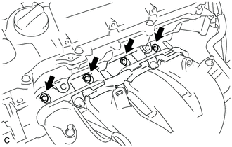
Remove the 4 injector vibration insulators from the cylinder head sub-assembly.