2ZR-FE ENGINE MECHANICAL CAMSHAFT REMOVAL
PROCEDURE

 55701J
1.REMOVE OUTER COWL TOP PANEL SUB-ASSEMBLY
55701J
1.REMOVE OUTER COWL TOP PANEL SUB-ASSEMBLY
11212
2.REMOVE NO. 2 CYLINDER HEAD COVER
19500
3.REMOVE IGNITION COIL ASSEMBLY
17705
4.REMOVE AIR CLEANER CAP WITH AIR CLEANER HOSE
82121
5.DISCONNECT ENGINE WIRE
17361M
6.REMOVE AIR TUBE
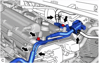
Slide the 3 clips and disconnect the union to connector tube hose, No. 1 fuel vapor feed hose, No. 2 fuel vapor feed hose and No. 1 vacuum transmitting hose.
Remove the 2 bolts and air tube.
11201
7.REMOVE CYLINDER HEAD COVER SUB-ASSEMBLY
11213
8.REMOVE CYLINDER HEAD COVER GASKET
9.SET NO. 1 CYLINDER TO TDC/COMPRESSION
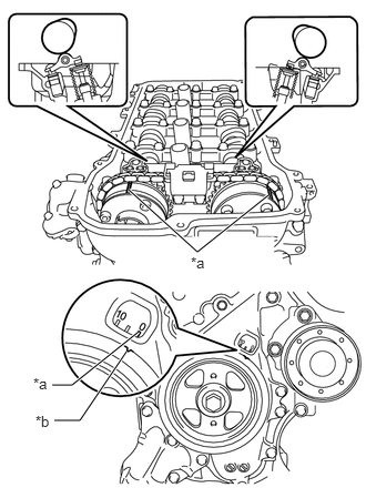
| *a | Timing Mark |
| *b | Timing Notch |
Turn the crankshaft pulley until its timing notch (groove) and the timing mark "0" of the timing chain cover sub-assembly are aligned.
Check that each timing mark of the camshaft timing gear assembly and camshaft timing exhaust gear assembly are aligned as shown in the illustration.
If not, turn the crankshaft 1 revolution (360°) to align the timing marks as shown in the illustration.
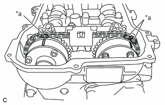
| *a | Paint Mark |
Place paint marks on the chain sub-assembly in alignment with the timing marks on the camshaft timing gear assembly and camshaft timing exhaust gear assembly.
13562
10.REMOVE NO. 2 CHAIN VIBRATION DAMPER
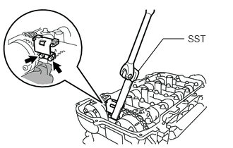
Using SST, remove the 2 bolts and No. 2 chain vibration damper from the camshaft bearing cap.
- SST
- 09961-00950
13540
11.REMOVE NO. 1 CHAIN TENSIONER ASSEMBLY
13070A
12.REMOVE CAMSHAFT TIMING EXHAUST GEAR ASSEMBLY
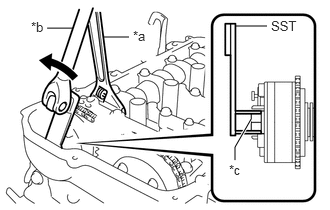
| *a | Hold |
| *b | Turn |
| *c | Bolt |
While holding the hexagonal portion of the No. 2 camshaft with a wrench, loosen the bolt with SST.
- SST
- 09249-37010
- NOTICE:
-
Do not remove the other 4 bolts ("TORX" bolt). If any of them is removed, replace the camshaft timing exhaust gear assembly.
- HINT:
-
The bolt cannot be removed separately from the camshaft timing exhaust gear assembly due to lack of space.
Hold the hexagonal portion of the camshaft with a wrench and turn the camshaft slightly counterclockwise to release the chain sub-assembly.
- NOTICE:
-
Do not turn the camshaft more than necessary.
- HINT:
-
Be sure to loosen the chain sub-assembly because the camshaft timing exhaust gear assembly cannot be removed with the chain tensioned.
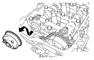
While removing the chain sub-assembly, pull out the camshaft timing exhaust gear assembly horizontally and then upward with the bolts installed.
13070A
13.INSPECT CAMSHAFT TIMING EXHAUST GEAR ASSEMBLY
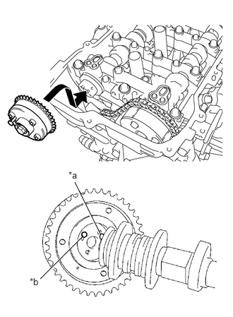
| *a | Straight Pin |
| *b | Pin Hole |
Temporarily install the camshaft timing exhaust gear assembly.
Insert the bolt into the camshaft timing exhaust gear assembly.
Align the straight pin on the No. 2 camshaft with the pin hole in the camshaft timing exhaust gear assembly and temporarily install the camshaft timing exhaust gear assembly to the No. 2 camshaft with the bolt.
- NOTICE:
- ·
Do not install the chain sub-assembly onto the camshaft timing exhaust gear assembly in this step.
- ·
Do not allow the chain sub-assembly to interfere with the camshaft timing exhaust gear assembly when installing the camshaft timing exhaust gear assembly.
Inspect the lock of the camshaft timing exhaust gear assembly.
Check that the camshaft timing exhaust gear assembly is locked.
If the camshaft timing exhaust gear assembly does not operate as specified, replace it.
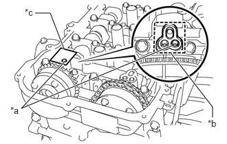
| *a | Make a Hole |
| *b | Adhesive Tape Sealing Area |
| *c | Adhesive Tape |
Inspect camshaft timing exhaust gear assembly operation.
- HINT:
-
If the camshaft timing exhaust gear assembly does not operate as specified, replace it.
After cleaning the exhaust side VVT oil hole in the camshaft bearing cap, completely seal the oil hole with adhesive tape or equivalent as shown in the illustration to prevent air from leaking.
- NOTICE:
-
Be sure to seal the oil hole completely because air leaks due to insufficient sealing will prevent the lock pin from being released.
Make a hole in the adhesive tape covering the oil hole as shown in the illustration. (Procedure A)
| *a | Protective Tape |
Apply approximately 200 kPa (2.0 kgf/cm2, 29 psi) of air pressure into the hole pricked in procedure A to release the lock pin.
- NOTICE:
- ·
If air leaks out, reattach the adhesive tape.
- ·
Cover the oil hole with a piece of cloth when applying air pressure to prevent oil from spraying.
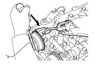
Using a screwdriver with its tip wrapped with protective tape, forcibly turn the camshaft timing exhaust gear assembly in the retard direction (clockwise).
- NOTICE:
- ·
Be sure to keep the camshaft timing exhaust gear assembly in the retard direction. If the camshaft timing exhaust gear assembly is released, it will return to the advanced position automatically due to the force from the spring.
- ·
Do not damage the camshaft timing exhaust gear assembly.
- HINT:
-
Depending on the air pressure applied, the camshaft timing exhaust gear assembly may turn in the retard direction without assistance by hand.
| *a | Protective Tape |
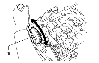
Using a screwdriver with its tip wrapped with protective tape, turn the camshaft timing exhaust gear assembly within its movable range (19 to 21°) 2 or 3 times without turning it to the most advanced position. Check that the camshaft timing exhaust gear assembly turns smoothly.
Lock the camshaft timing exhaust gear assembly.
- NOTICE:
-
Check that the camshaft timing exhaust gear assembly locks at the most advanced position (the most advanced position of its movable range) and cannot be rotated any further.
Remove the adhesive tape from the camshaft bearing cap.
Remove the camshaft timing exhaust gear assembly.
Remove the temporarily installed camshaft timing exhaust gear assembly.
13050
14.INSPECT CAMSHAFT TIMING GEAR ASSEMBLY
Inspect the lock of the camshaft timing gear assembly.
Check that the camshaft timing gear assembly is locked.
If the camshaft timing gear assembly does not operate as specified, replace it.
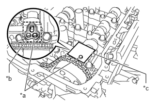
| *a | Make a Hole |
| *b | Adhesive Tape Sealing Area |
| *c | Adhesive Tape |
Inspect camshaft timing gear assembly operation.
- HINT:
-
If the camshaft timing gear assembly does not operate as specified, replace it.
After cleaning the intake side VVT oil hole in the camshaft bearing cap, completely seal the oil hole with adhesive tape or equivalent as shown in the illustration to prevent air from leaking.
- NOTICE:
-
Be sure to seal the oil hole completely because air leaks due to insufficient sealing will prevent the lock pin from being released.
Make a hole in the adhesive tape covering the oil hole as shown in the illustration. (Procedure B)
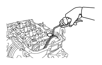
Apply approximately 150 kPa (1.5 kgf/cm2, 22 psi) of air pressure into the hole made in procedure B to release the lock pin.
- NOTICE:
- ·
If air leaks out, reattach the adhesive tape.
- ·
Cover the oil hole with a piece of cloth when applying air pressure to prevent oil from spraying.
Forcibly turn the camshaft timing gear assembly in the advance direction (counterclockwise).
- HINT:
-
Depending on the air pressure applied, the camshaft timing gear assembly may turn in the advance direction without assistance by hand.
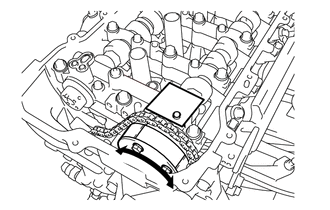
Turn the camshaft timing gear assembly within its movable range (20.5 to 22.5°) 2 or 3 times without turning it to the most retarded position. Check that the camshaft timing gear assembly turns smoothly.
- NOTICE:
- ·
Do not lock the camshaft timing gear assembly.
- ·
If the camshaft timing gear assembly is locked, release the lock pin again.
Remove the adhesive tape from the camshaft bearing cap.
15.REMOVE CAMSHAFT BEARING CAP
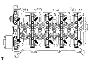
Uniformly loosen and remove the 10 bolts in the order shown in the illustration.
- NOTICE:
-
Do not loosen the other 15 bearing cap bolts in this step.
- HINT:
-
Arrange the removed parts in the correct order.
Remove the bolts and camshaft bearing caps in the order shown in the illustration. Immediately after removing the camshaft bearing caps, install service bolts and spacers in the order shown in the illustration.
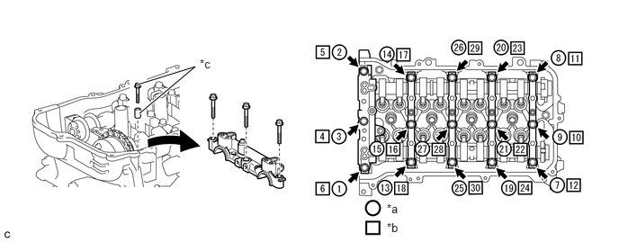
| *a | The removal order of the parts | *b | The installation order of the service bolts and spacers for temporarily tightening the camshaft housing sub-assembly |
| *c | Service bolt and spacer (Used to temporarily secure the camshaft housing sub-assembly) | - | - |
- Torque:
- 27 N*m (275 kgf*cm, 20 ft.*lbf)
- NOTICE:
- ·
If the bolts are loosened all at once, FIPG on the camshaft housing sub-assembly and cylinder head sub-assembly may peel off, resulting in oil oozing. Therefore, be sure to install the service bolts and spacers to one camshaft bearing cap at a time.
- ·
Do not install the camshaft bearing caps when installing the service bolts and spacers.
- HINT:
- ·
Arrange the removed parts in the correct order.
- ·
Part number for the service bolts used to temporarily secure the camshaft housing sub-assembly: 91551-G0875 (15 bolts)
- ·
Part number for the spacers used to temporarily secure the camshaft housing sub-assembly: 90387-12048 (15 spacers)
13512
16.REMOVE NO. 2 CAMSHAFT
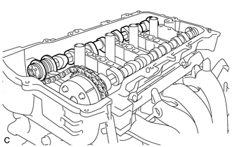
Remove the No. 2 camshaft from the camshaft housing sub-assembly.
13511
17.REMOVE CAMSHAFT
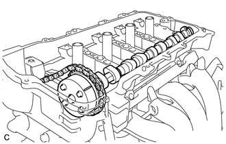
Hold up the chain sub-assembly and remove the camshaft from the camshaft housing sub-assembly.
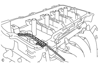
Suspend the chain sub-assembly with a string or equivalent.
13050
18.REMOVE CAMSHAFT TIMING GEAR ASSEMBLY
Secure the hexagonal portion of the camshaft in a soft jaw vise.
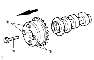
| *a | Bolt |
| *b | Do not remove |
Remove the bolt and camshaft timing gear assembly.
- NOTICE:
- ·
Before removing the camshaft timing gear assembly, make sure that the lock pin has been released.
- ·
Do not remove the other 4 bolts.
- ·
Keep the camshaft timing gear assembly horizontal while removing it from the camshaft.
- ·
If the camshaft timing gear assembly is to be reused, be sure to use it with the lock pin released.
11811
19.REMOVE NO. 1 CAMSHAFT BEARING
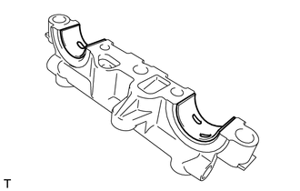
Remove the 2 No. 1 camshaft bearings from the camshaft bearing cap.
- NOTICE:
-
Arrange the removed parts in the correct order.
11821
20.REMOVE NO. 2 CAMSHAFT BEARING
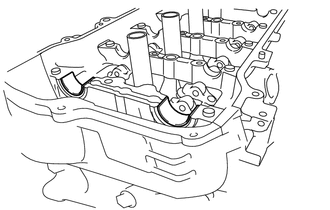
Remove the 2 No. 2 camshaft bearings from the camshaft housing sub-assembly.
- NOTICE:
-
Arrange the removed parts in the correct order.