THEFT DETERRENT / KEYLESS ENTRY SMART ENTRY AND START SYSTEM(for Start Function) B2282 Vehicle Speed Signal Malfunction B2283 Vehicle Speed Sensor Malfunction
DESCRIPTION
DTC B2282 is stored when the vehicle speed signal sent by the combination meter assembly via direct line and the vehicle speed signal sent via CAN communication do not match.
DTC B2283 is stored when a malfunction in the vehicle speed sensor is detected.
| DTC No. | Detection Item | DTC Detection Condition | Trouble Area | Note |
|---|---|---|---|---|
| B2282 | Vehicle Speed Signal Malfunction | The vehicle speed signal sent by the combination meter assembly via direct line and the vehicle speed signal sent via CAN communication do not match. (1-trip detection logic*) | ·
AM2 fuse ·
Meter/gauge system ·
Certification ECU (smart key ECU assembly) ·
Wire harness or connector |
DTC Output Confirmation Operation
Drive the vehicle for 20 seconds at a vehicle speed of 25 km/h (16 mph) or more, and then drive the vehicle at a vehicle speed of less than 5 km/h (3 mph) for 20 seconds. |
| B2283 | Vehicle Speed Sensor Malfunction | Either of the following malfunctions is detected (a vehicle speed sensor malfunction is detected) (1-trip detection logic*)
·
Vehicle speed signal malfunction detection 1: Excessive deceleration is detected ·
Vehicle speed signal malfunction detection 2: Engine speed linked detection |
·
AM2 fuse ·
Meter/gauge system ·
Certification ECU (smart key ECU assembly) ·
Wire harness or connector |
DTC Output Confirmation Operation
Run the engine at an engine speed of 2000 rpm or more for 330 seconds. |
*: Only detected while a malfunction is present and the engine switch is on (IG).
| DTC Code | Vehicle Condition when Malfunction Detected | Fail-safe Function when Malfunction Detected |
|---|---|---|
| B2282 | ·
When the signal from the direct line or CAN communication is malfunctioning and indicates that the vehicle speed is 0 km/h (0 mph), there is no effect on vehicle behavior. ·
When the signal from the direct line or CAN communication is malfunctioning and indicates that the vehicle is moving, the engine switch cannot be turned from on (IG) to off. |
- |
| B2283 | ·
The power source mode is changed to off (the engine is stopped) by pressing the engine switch while the vehicle is being driven. ·
With the electrical key transmitter sub-assembly in the cabin, even if an engine start operation is performed, the engine does not start. |
Steering lock motor operation is prohibited. |
| DTC No. | Data List Item | Active Test Item |
|---|---|---|
| B2282
B2283 |
Power Source Control
·
Vehicle Speed Signal ·
Engine Condition ·
Power Supply Condition Starting Control
·
Engine Speed Combination Meter
·
Vehicle Speed Meter |
- |
WIRING DIAGRAM
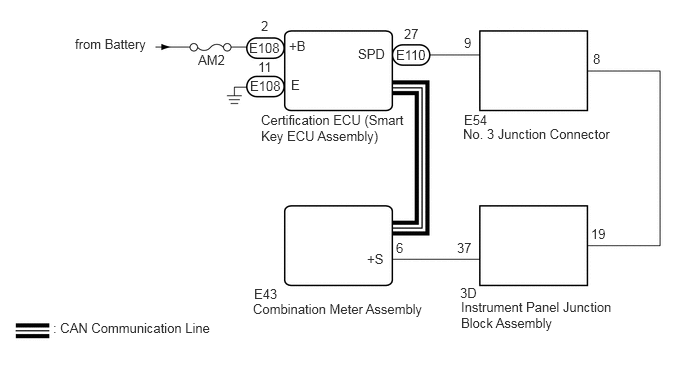
CAUTION / NOTICE / HINT
- NOTICE:
- ·
When using the GTS with the engine switch off, connect the GTS to the DLC3 and turn a courtesy light switch on and off at intervals of 1.5 seconds or less until communication between the GTS and the vehicle begins. Then select Model Code "KEY REGIST" under manual mode and enter the following menus: Body Electrical / Entry&Start(CAN). While using the GTS, periodically turn a courtesy light switch on and off at intervals of 1.5 seconds or less to maintain communication between the GTS and the vehicle.
·The smart entry and start system (for Start Function) uses the LIN communication system and CAN communication system. Inspect the communication function by following How to Proceed with Troubleshooting. Troubleshoot the smart entry and start system (for Start Function) after confirming that the communication systems are functioning properly.
·Before replacing the certification ECU (smart key ECU assembly), refer to smart entry and start system (for Start Function) Precaution.
·Inspect the fuses of circuits related to this system before performing the following procedure.
·After performing repairs, perform the operation that fulfills the DTC output confirmation operation, and then confirm that no DTCs are output again.
- HINT:
-
When the cable is disconnected and reconnected to the negative (-) battery terminal, the power source mode returns to the state it was in before the cable was disconnected.
PROCEDURE
Connect the GTS to the DLC3.
Turn the engine switch on (IG).
Turn the GTS on.
Enter the following menus: Body Electrical / Combination Meter / Data List.
Read the Data List according to the display on the GTS.
- Body Electrical > Combination Meter > Data List
-
Tester Display Measurement Item Range Normal Condition Diagnostic Note Vehicle Speed Meter Vehicle speed 0 to 255 Almost same as actual vehicle speed -
- Body Electrical > Combination Meter > Data List
-
Tester Display Vehicle Speed Meter - 50003 122 8
- OK:
The GTS display changes correctly in response to the vehicle condition.
- Result:
Proceed to OK NG
OK
NG
Enter the following menus: Body Electrical / Power Source Control / Data List.
Read the Data List according to the display on the GTS.
- Body Electrical > Power Source Control > Data List
-
Tester Display Measurement Item Range Normal Condition Diagnostic Note Vehicle Speed Signal Vehicle being driven or stopped Stop or Run Stop: Vehicle stopped
Run: Vehicle being driven at 5 km/h (3 mph) or more-
- Body Electrical > Power Source Control > Data List
-
Tester Display Vehicle Speed Signal - 50003 223 16
- OK:
The GTS display changes correctly in response to the vehicle condition.
- Result:
Proceed to OK NG
OK
Click hereVehicle Interior>METER / GAUGE / DISPLAY>METER / GAUGE SYSTEM>HOW TO PROCEED WITH TROUBLESHOOTING
NG
- Result:
Proceed to OK NG
OK
NG
- Result:
Proceed to OK NG
OK
NG
Disconnect the E110 certification ECU (smart key ECU assembly) connector.
Disconnect the E43 combination meter assembly connector.
Measure the resistance according to the value(s) in the table below.
- Standard Resistance:
Tester Connection Condition Specified Condition E110-27 (SPD) - E43-6 (+S) Always Below 1 Ω E110-27 (SPD) or E43-6 (+S) - Body ground Always 10 kΩ or higher
- Result:
Proceed to OK NG
OK
NG
Reconnect the E108 and E110 certification ECU (smart key ECU assembly) connectors.
Reconnect the E43 combination meter assembly connector.
Using an oscilloscope, check the waveform.
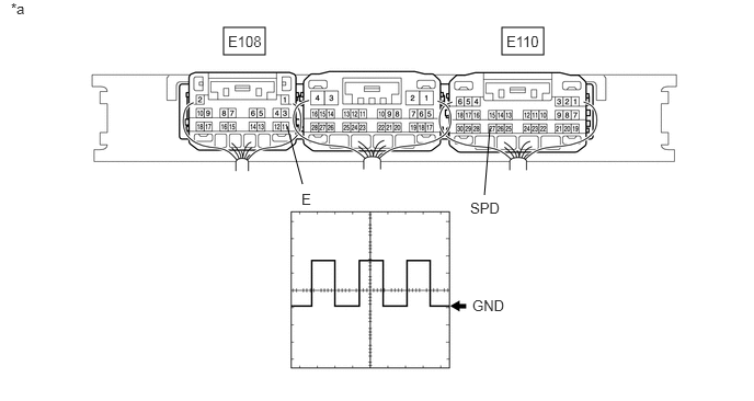
| *a | Component with harness connected
(Certification ECU (Smart Key ECU Assembly)) |
- | - |
| Tester Connection | Condition | Tool Setting | Specified Condition |
|---|---|---|---|
| E110-27 (SPD) - E108-11 (E) | Engine switch on (IG), vehicle being driven at approx. 5 km/h (3 mph) | 5 V/DIV., 20 ms./DIV. | Pulse generation |
- HINT:
-
When the system is functioning normally, one wheel revolution generates 4 pulses. As the vehicle speed increases, the width indicated by (A) in the illustration narrows.
- OK:
The waveform is similar to that shown in the illustration.
- Result:
Proceed to OK NG
OK
NG
Disconnect the 3D instrument panel junction block assembly connector.
Measure the resistance according to the value(s) in the table below.
- Standard Resistance:
Tester Connection Condition Specified Condition E43-6 (+S) - 3D-37 Always Below 1 Ω E43-6 (+S) or 3D-37 - Body ground Always 10 kΩ or higher
- Result:
Proceed to OK NG
OK
NG
Remove the instrument panel junction block assembly.
Click herePower Source / Network>POWER DISTRIBUTION>MAIN BODY ECU>REMOVAL
Measure the resistance according to the value(s) in the table below.
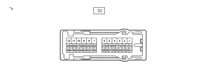
| *a | Component without harness connected
(Instrument Panel Junction Block Assembly) |
- | - |
- Standard Resistance:
Tester Connection Condition Specified Condition 3D-19 - 3D-37 Always Below 1 Ω
- Result:
Proceed to OK NG
OK
NG
Measure the resistance according to the value(s) in the table below.
- Standard Resistance:
Tester Connection Condition Specified Condition E110-27 (SPD) - 3D-19 Always Below 1 Ω E110-27 (SPD) or 3D-19 - Body ground Always 10 kΩ or higher
- Result:
Proceed to OK NG
OK
NG
Disconnect the E54 No. 3 junction connector connector.
Measure the resistance according to the value(s) in the table below.
- Standard Resistance:
Tester Connection Condition Specified Condition E54-8 - 3D-19 Always Below 1 Ω E54-8 or 3D-19 - Body ground Always 10 kΩ or higher
- Result:
Proceed to OK NG
OK
NG
Measure the resistance according to the value(s) in the table below.
- Standard Resistance:
Tester Connection Condition Specified Condition E110-27 (SPD) - E54-9 Always Below 1 Ω E110-27 (SPD) or E54-9 - Body ground Always 10 kΩ or higher
- Result:
Proceed to OK NG
OK
NG