BRAKE CONTROL / DYNAMIC CONTROL SYSTEMS VEHICLE STABILITY CONTROL SYSTEM Slip Indicator Light Remains ON
DESCRIPTION
The skid control ECU (brake actuator assembly) is connected to the combination meter assembly via CAN communication.
The slip indicator light blinks during VSC and/or TRC operation.
If a malfunction is detected, the slip indicator light comes on to warn the driver.
Click hereBrake>BRAKE CONTROL / DYNAMIC CONTROL SYSTEMS>VEHICLE STABILITY CONTROL SYSTEM>DIAGNOSIS SYSTEM
WIRING DIAGRAM
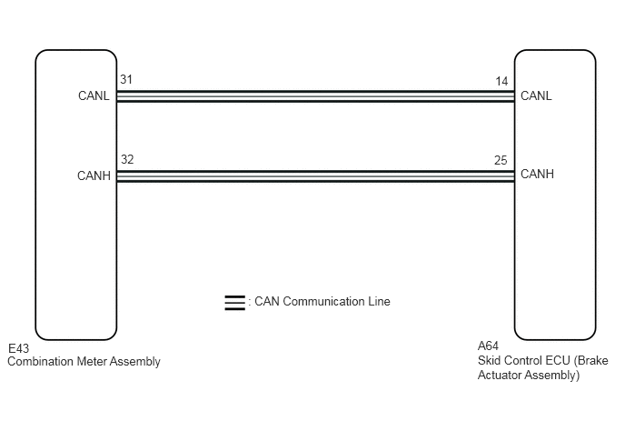
CAUTION / NOTICE / HINT
- NOTICE:
-
When replacing the skid control ECU (brake actuator assembly), perform zero point calibration.
-
Click hereBrake>BRAKE CONTROL / DYNAMIC CONTROL SYSTEMS>VEHICLE STABILITY CONTROL SYSTEM>CALIBRATION
PROCEDURE
Check if CAN communication system DTCs are output.
Click herePower Source / Network>NETWORKING>CAN COMMUNICATION SYSTEM>DIAGNOSIS SYSTEM
- Result:
Result Proceed to DTCs are not output. A DTCs are output. B
A
B
Click herePower Source / Network>NETWORKING>CAN COMMUNICATION SYSTEM>HOW TO PROCEED WITH TROUBLESHOOTING
Check if the skid control ECU (brake actuator assembly) connector is securely connected.
- OK:
The connector is securely connected.
- Result:
Proceed to OK NG
OK
NG
Check the battery voltage.
- Standard Voltage:
11 to 14 V
- Result:
Proceed to OK NG
OK
NG
Connect the GTS to the DLC3.
Turn the engine switch on (IG).
Select the Data List on the GTS.
- Chassis > ABS/VSC/TRC > Data List
-
Tester Display Measurement Item Range Normal Condition Diagnostic Note Slip Indicator Light Slip indicator light ON or OFF ON: Indicator light on
OFF: Indicator light off-
- Chassis > ABS/VSC/TRC > Data List
-
Tester Display Slip Indicator Light - 50003 105 53
Check the GTS display condition of the slip indicator light.
- Result:
Result Proceed to OFF is displayed. A ON is displayed. B
- HINT:
-
If troubleshooting has been carried out according to Problem Symptoms Table, refer back to the table and proceed to the next step before replacing the parts.
A
Click hereVehicle Interior>METER / GAUGE / DISPLAY>METER / GAUGE SYSTEM>HOW TO PROCEED WITH TROUBLESHOOTING
B