POWER ASSIST SYSTEMS POWER STEERING SYSTEM C1524 Motor Terminal Voltage C1555 Motor Relay Welding Failure
DESCRIPTION
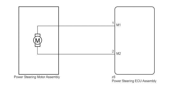
The power steering ECU assembly supplies current to the power steering motor assembly through the motor circuit.
| DTC No. | Detection Item | DTC Detection Condition | Trouble Area | Warning Indicate | Return-to-normal Condition | Note |
|---|---|---|---|---|---|---|
| C1524 | Motor Terminal Voltage | Short (or open) in motor circuit or abnormal voltage in motor circuit | ·
Power steering motor assembly ·
Power steering ECU assembly |
EPS warning light: Comes on | Ignition switch ON again | - |
| C1555 | Motor Relay Welding Failure | Predriver (Motor relay circuit) malfunction | ·
Power steering motor assembly ·
Power steering ECU assembly |
EPS warning light: Comes on | Ignition switch ON again | - |
WIRING DIAGRAM
0.583,3.135 2.583,3.313
2,0.177
10
false
Power Steering Motor Assembly
4.688,3.135 5.01,3.385
0.323,0.25
10
false
z8
4.875,2.156 5.094,2.333
0.219,0.177
10
false
M2
4.698,2.063 4.792,2.24
0.094,0.177
10
false
2
4.875,0.958 5.094,1.135
0.219,0.177
10
false
M1
4.698,0.875 4.792,1.052
0.094,0.177
10
false
1
4.688,3.302 6.625,3.479
1.938,0.177
10
false
Power Steering ECU Assembly
CAUTION / NOTICE / HINT
- NOTICE:
-
If the power steering ECU assembly has been replaced, perform assist map writing and torque sensor zero point calibration.
-
Click hereSteering>POWER ASSIST SYSTEMS>POWER STEERING SYSTEM>CALIBRATION
PROCEDURE
1.CHECK POWER STEERING ECU ASSEMBLY
a.
Start the engine.
b.
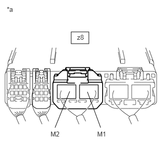
1.51,0.677 1.885,0.927
0.375,0.25
1.479,1.938 1.167,2.708
false
1.854,1.948 2.135,2.708
false
1.635,0.708 2.271,1.115
0.635,0.406
10
false
z8
1.073,2.76 1.802,3.24
0.729,0.479
10
false
M2
2.063,2.76 2.604,3.135
0.542,0.375
10
false
M1
0.146,0.115 0.823,0.76
0.677,0.646
10
false
*a
| *a | Component with harness connected
(Power Steering ECU Assembly) |
Measure the voltage according to the value(s) in the table below.
- Standard Voltage:
Tester Connection Condition Specified Condition z8-1 (M1) - Body ground Engine running and steering wheel being turned to left 6 to 8 V z8-1 (M1) - Body ground Engine running and steering wheel being turned to right 9 to 16 V z8-2 (M2) - Body ground Engine running and steering wheel being turned to left 9 to 16 V z8-2 (M2) - Body ground Engine running and steering wheel being turned to right 6 to 8 V
- Result:
Proceed to OK NG
OK
2.INSPECT POWER STEERING MOTOR ASSEMBLY
NG
REPLACE POWER STEERING ECU ASSEMBLY
2.INSPECT POWER STEERING MOTOR ASSEMBLY
a.
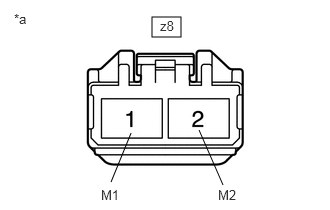
Disconnect the z8 power steering ECU assembly connector.
b.
1.583,0.177 1.885,0.385
0.302,0.208
1.365,1.385 1.156,1.896
false
2.073,1.354 2.323,1.927
false
1.667,0.188 2.063,0.438
0.396,0.25
10
false
z8
1.052,1.948 1.438,2.177
0.385,0.229
10
false
M1
2.271,1.948 2.677,2.177
0.406,0.229
10
false
M2
0.146,0.115 0.385,0.438
0.24,0.323
10
false
*a
| *a | Front view of wire harness connector
(to Power Steering ECU Assembly) |
Measure the resistance according to the value(s) in the table below.
- Standard Resistance:
Tester Connection Condition Specified Condition z8-1 (M1) - z8-2 (M2) Always 0.1 to 1.0 Ω z8-1 (M1) or z8-2 (M2) - Body ground Always 1 MΩ or higher
- Result:
Proceed to OK NG
OK
REPLACE POWER STEERING ECU ASSEMBLY
NG
REPLACE POWER STEERING MOTOR ASSEMBLY