HEATING / AIR CONDITIONING  AIR CONDITIONING SYSTEM(for Manual Air Conditioning System)  Blower Motor Circuit  


DESCRIPTION

When the No. 2 heater control sub-assembly is operated, the heater relay will turn on to allow current to flow to the blower motor and then the motor will start rotating. Operating the No. 2 heater control sub-assembly switches the current flow between the blower resistor and body ground, thus, shifting the rotation speed of the blower motor with fan sub-assembly.

WIRING DIAGRAM
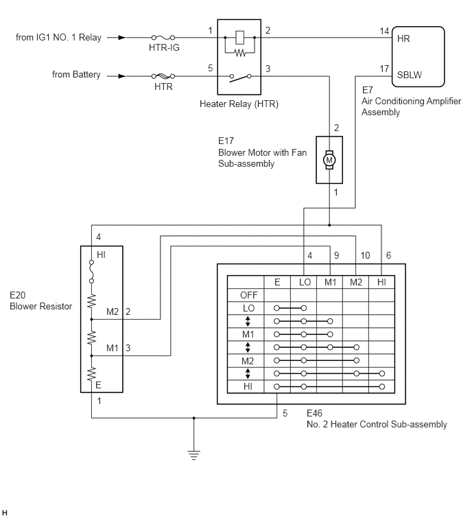
E279969E05
0.24,0.479 1.719,0.729 1.479,0.25 10 false from IG1 NO. 1 Relay 0.792,1.042 1.74,1.302 0.948,0.26 10 false from Battery 2.26,0.635 3.177,0.833 0.917,0.198 10 false HTR-IG 2.344,1.229 2.698,1.542 0.354,0.313 10 false HTR 3.156,0.375 3.313,0.573 0.156,0.198 10 false 1 3.156,0.948 3.313,1.146 0.156,0.198 10 false 5 4.031,0.375 4.188,0.573 0.156,0.198 10 false 2 4.031,0.958 4.188,1.156 0.156,0.198 10 false 3 3.031,1.49 4.333,1.719 1.302,0.229 10 false Heater Relay (HTR) 5.76,0.385 6.021,0.656 0.26,0.271 10 false 14 5.76,0.958 6.021,1.229 0.26,0.271 10 false 17 6.031,0.5 6.344,0.698 0.313,0.198 10 false HR 6.031,1.052 6.594,1.281 0.563,0.229 10 false SBLW 5.5,1.281 5.958,1.479 0.458,0.198 10 false E7 5.49,1.448 7.063,1.823 1.573,0.375 10 false Air Conditioning Amplifier Assembly 5.073,1.854 5.229,2.052 0.156,0.198 10 false 2 5.063,2.833 5.219,3.031 0.156,0.198 10 false 1 3.313,2.052 3.771,2.25 0.458,0.198 10 false E17 3.313,2.229 4.729,2.708 1.417,0.479 10 false Blower Motor with Fan Sub-assembly 0.146,4.396 0.604,4.594 0.458,0.198 10 false E20 0.146,4.563 1.25,4.792 1.104,0.229 10 false Blower Resistor 1.458,3.51 2.135,3.75 0.677,0.24 10 false 4 1.469,3.781 1.781,3.979 0.313,0.198 10 false HI 1.615,4.646 1.927,4.844 0.313,0.198 10 false M2 1.615,5.198 1.927,5.396 0.313,0.198 10 false M1 1.906,4.646 2.479,4.865 0.573,0.219 10 false 2 1.906,5.198 2.479,5.417 0.573,0.219 10 false 3 1.469,6 2.042,6.219 0.573,0.219 10 false 1 1.448,5.76 1.604,5.958 0.156,0.198 10 false E 4.292,6.188 4.448,6.385 0.156,0.198 10 false 5 4.656,6.188 5.115,6.385 0.458,0.198 10 false E46 4.656,6.354 7.104,6.625 2.448,0.271 10 false No. 2 Heater Control Sub-assembly 4.667,3.792 4.823,3.99 0.156,0.198 10 false 4 5.073,3.792 5.229,3.99 0.156,0.198 10 false 9 5.469,3.792 5.76,4.042 0.292,0.25 10 false 10 5.865,3.792 6.156,4.042 0.292,0.25 10 false 6 3.646,4.396 4.063,4.604 0.417,0.208 10 false OFF 3.688,4.594 3.948,4.792 0.26,0.198 10 false LO 3.677,4.99 3.99,5.188 0.313,0.198 10 false M1 3.667,5.396 3.979,5.594 0.313,0.198 10 false M2 3.698,5.781 4.01,5.99 0.313,0.208 10 false HI 4.167,4.198 4.323,4.396 0.156,0.198 10 false E 4.542,4.198 4.802,4.396 0.26,0.198 10 false LO 4.927,4.198 5.24,4.396 0.313,0.198 10 false M1 5.313,4.198 5.625,4.396 0.313,0.198 10 false M2 5.729,4.198 6.042,4.406 0.313,0.208 10 false HI

CAUTION / NOTICE / HINT

NOTICE:

Inspect the fuses for circuits related to this system before performing the following procedure.


PROCEDURE
1.INSPECT HEATER RELAY (HTR)
a.
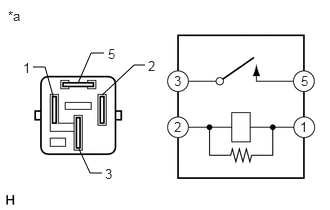
E218162C10
0.813,0.865 0.948,0.552 0.948,0.552 1.083,0.552 false 1.063,0.99 1.396,0.677 1.396,0.677 1.51,0.677 false 0.552,1 0.469,0.698 0.469,0.698 0.344,0.698 false 1.063,1.802 0.938,1.802 0.938,1.802 0.823,1.552 false 1.813,1.24 2.063,1.49 0.25,0.25 10 false 2 1.813,0.76 2.063,1.01 0.25,0.25 10 false 3 3.135,0.76 3.385,1.01 0.25,0.25 10 false 5 3.125,1.24 3.375,1.49 0.25,0.25 10 false 1 0.24,0.625 0.49,0.875 0.25,0.25 10 false 1 1.094,1.729 1.344,1.979 0.25,0.25 10 false 3 1.542,0.604 1.792,0.854 0.25,0.25 10 false 2 1.125,0.479 1.375,0.729 0.25,0.25 10 false 5 0.083,0.083 0.25,0.25 0.167,0.167 10 false *a
*a Component without harness connected
(Heater Relay (HTR))


Remove the heater relay (HTR).


b.

Measure the resistance according to the value(s) in the table below.

Standard Resistance:
Tester Connection Condition Specified Condition
3 - 5 Battery voltage not applied between terminals 1 and 2 10 kΩ or higher
3 - 5 Battery voltage applied between terminals 1 and 2 Below 1 Ω


Result:
Proceed to
OK
NG


OK

2.INSPECT BLOWER MOTOR WITH FAN SUB-ASSEMBLY

NG

REPLACE HEATER RELAY (HTR)

2.INSPECT BLOWER MOTOR WITH FAN SUB-ASSEMBLY
a.

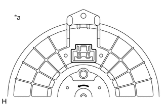
Disconnect the E17 blower motor with fan sub-assembly connector.

b.
E282261C01
0.292,0.271 0.604,0.469 0.313,0.198 10 false *a
*a Component without harness connected
(Blower Motor with Fan Sub-assembly)


Connect a positive (+) lead from the battery to terminal 2 and a negative (-) lead to terminal 1, and check that the motor operates.

OK:

The blower motor with fan sub-assembly operates smoothly.


Result:
Proceed to
OK
NG


OK

3.INSPECT BLOWER RESISTOR

NG

REPLACE BLOWER MOTOR WITH FAN SUB-ASSEMBLY

3.INSPECT BLOWER RESISTOR
a.
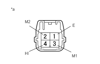
E145426C14
1.979,1.167 2.427,0.896 false 1.479,1.177 1.01,0.885 false 1.979,1.552 2.448,1.781 false 1.469,1.552 1,1.76 false 0.375,0.229 0.823,0.656 0.448,0.427 10 false *a 2.49,0.781 2.813,1.042 0.323,0.26 10 false E 0.854,0.656 1.302,1.021 0.448,0.365 10 false M2 2.469,1.823 3.271,2.167 0.802,0.344 10 false M1 0.854,1.74 1.385,2.073 0.531,0.333 10 false HI
*a Component without harness connected
(Blower Resistor)


Remove the blower resistor.

Click hereVehicle Interior>HEATING / AIR CONDITIONING>BLOWER RESISTOR>REMOVAL


b.

Measure the resistance according to the value(s) in the table below.

Standard Resistance:
Tester Connection Condition Specified Condition
1 (E) - 4 (HI) Always 3.12 to 3.60 Ω
3 (M1) - 4 (HI) Always 1.45 to 1.67 Ω
2 (M2) - 4 (HI) Always 0.52 to 0.60 Ω


Result:
Proceed to
OK
NG


OK

4.INSPECT NO. 2 HEATER CONTROL SUB-ASSEMBLY

NG

4.INSPECT NO. 2 HEATER CONTROL SUB-ASSEMBLY
a.
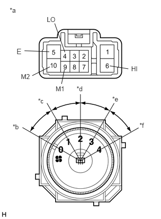
E277675C05
0.688,1.615 1.063,1.427 false 2.344,1.406 2.74,1.469 false 1.313,1.792 1.375,1.49 false 0.521,1.083 1.052,1.104 false 1.385,1.115 1.167,0.5 false 0.208,0.135 0.521,0.333 0.313,0.198 10 false *a 0.354,1 0.667,1.198 0.313,0.198 11 false E 1,0.333 1.313,0.531 0.313,0.198 10 false LO 0.448,1.552 0.76,1.75 0.313,0.198 10 false M2 1.188,1.813 1.5,2.01 0.313,0.198 10 false M1 2.802,1.385 3.115,1.583 0.313,0.198 10 false HI 0.271,2.625 0.469,2.833 0.198,0.208 10 false *b 0.813,2.073 1.01,2.281 0.198,0.208 10 false *c 1.635,1.813 1.833,2.021 0.198,0.208 10 false *d 2.396,2.031 2.594,2.24 0.198,0.208 10 false *e 2.979,2.594 3.177,2.802 0.198,0.208 10 false *f
*a Component without harness connected
(No. 2 Heater Control Sub-assembly)
*b Blower Switch OFF Position
*c Blower Switch LO Position
*d Blower Switch M1 Position
*e Blower Switch M2 Position
*f Blower Switch HI Position


Remove the No. 2 heater control sub-assembly.

Click hereVehicle Interior>HEATING / AIR CONDITIONING>AIR CONDITIONING PANEL(for Manual Air Conditioning System)>REMOVAL


b.

Measure the resistance according to the value(s) in the table below.

Standard Resistance:
Tester Connection Condition Specified Condition
4 (LO) - 5 (E) Blower switch: OFF 10 kΩ or higher
6 (HI) - 5 (E)
9 (M1) - 5 (E)
10 (M2) - 5 (E)
4 (LO) - 5 (E) Blower switch: LO Below 1 Ω
4 (LO) - 5 (E) Blower switch: LO - M1 Below 1 Ω
9 (M1) - 5 (E)
4 (LO) - 5 (E) Blower switch: M1 Below 1 Ω
9 (M1) - 5 (E)
4 (LO) - 5 (E) Blower switch: M1 - M2 Below 1 Ω
9 (M1) - 5 (E)
10 (M2) - 5 (E)
4 (LO) - 5 (E) Blower switch: M2 Below 1 Ω
10 (M2) - 5 (E)
4 (LO) - 5 (E) Blower switch: M2 - HI Below 1 Ω
6 (HI) - 5 (E)
10 (M2) - 5 (E)
4 (LO) - 5 (E) Blower switch: HI Below 1 Ω
6 (HI) - 5 (E)


Result:
Proceed to
OK
NG


OK

5.CHECK HARNESS AND CONNECTOR (HEATER RELAY (HTR) - POWER SOURCE)

NG

5.CHECK HARNESS AND CONNECTOR (HEATER RELAY (HTR) - POWER SOURCE)
a.

Measure the voltage according to the value(s) in the table below.

Standard Voltage:
Tester Connection Condition Specified Condition
Heater relay (HTR) terminal 1 - Body ground Ignition switch ON 11 to 14 V
Heater relay (HTR) terminal 5 - Body ground Always 11 to 14 V


Result:
Proceed to
OK
NG


OK

6.CHECK HARNESS AND CONNECTOR (AIR CONDITIONING AMPLIFIER ASSEMBLY - HEATER RELAY (HTR))

NG

REPAIR OR REPLACE HARNESS OR CONNECTOR

6.CHECK HARNESS AND CONNECTOR (AIR CONDITIONING AMPLIFIER ASSEMBLY - HEATER RELAY (HTR))
a.

Measure the resistance according to the value(s) in the table below.

Standard Resistance:
Tester Connection Condition Specified Condition
Heater relay (HTR) terminal 2 - E7-14 (HR) Always Below 1 Ω
Heater relay (HTR) terminal 2 - Body ground Always 10 kΩ or higher


Result:
Proceed to
OK
NG


OK

7.CHECK HARNESS AND CONNECTOR (NO. 2 HEATER CONTROL SUB-ASSEMBLY - AIR CONDITIONING AMPLIFIER ASSEMBLY)

NG

REPAIR OR REPLACE HARNESS OR CONNECTOR

7.CHECK HARNESS AND CONNECTOR (NO. 2 HEATER CONTROL SUB-ASSEMBLY - AIR CONDITIONING AMPLIFIER ASSEMBLY)
a.

Measure the resistance according to the value(s) in the table below.

Standard Resistance:
Tester Connection Condition Specified Condition
E7-17 (SBLW) - E46-4 (LO) Always Below 1 Ω
E7-17 (SBLW) - Body ground Always 10 kΩ or higher


Result:
Proceed to
OK
NG


OK

8.CHECK HARNESS AND CONNECTOR (BLOWER RESISTOR - NO. 2 HEATER CONTROL SUB-ASSEMBLY)

NG

REPAIR OR REPLACE HARNESS OR CONNECTOR

8.CHECK HARNESS AND CONNECTOR (BLOWER RESISTOR - NO. 2 HEATER CONTROL SUB-ASSEMBLY)
a.

Measure the resistance according to the value(s) in the table below.

Standard Resistance:
Tester Connection Condition Specified Condition
E20-4 (HI) - E46-6 (HI) Always Below 1 Ω
E20-2 (M2) - E46-10 (M2) Always Below 1 Ω
E20-3 (M1) - E46-9 (M1) Always Below 1 Ω
E20-1 (E) - Body ground Always Below 1 Ω
E46-5 (E) - Body ground Always Below 1 Ω
E20-4 (HI) - Body ground Always 10 kΩ or higher
E20-2 (M2) - Body ground Always 10 kΩ or higher
E20-3 (M1) - Body ground Always 10 kΩ or higher


Result:
Proceed to
OK
NG


OK

9.CHECK HARNESS AND CONNECTOR (BLOWER MOTOR WITH FAN SUB-ASSEMBLY - NO. 2 HEATER CONTROL SUB-ASSEMBLY)

NG

REPAIR OR REPLACE HARNESS OR CONNECTOR

9.CHECK HARNESS AND CONNECTOR (BLOWER MOTOR WITH FAN SUB-ASSEMBLY - NO. 2 HEATER CONTROL SUB-ASSEMBLY)
a.

Measure the resistance according to the value(s) in the table below.

Standard Resistance:
Tester Connection Condition Specified Condition
E17-1 - E46-6 (HI) Always Below 1 Ω
E17-1 - Body ground Always 10 kΩ or higher


Result:
Proceed to
OK
NG


OK

10.CHECK HARNESS AND CONNECTOR (BLOWER MOTOR WITH FAN SUB-ASSEMBLY - HEATER RELAY (HTR))

NG

REPAIR OR REPLACE HARNESS OR CONNECTOR

10.CHECK HARNESS AND CONNECTOR (BLOWER MOTOR WITH FAN SUB-ASSEMBLY - HEATER RELAY (HTR))
a.

Measure the resistance according to the value(s) in the table below.

Standard Resistance:
Tester Connection Condition Specified Condition
Heater relay (HTR) terminal 3 - E17-2 Always Below 1 Ω
Heater relay (HTR) terminal 3 - Body ground Always 10 kΩ or higher


Result:
Proceed to
OK
NG


OK

NG

REPAIR OR REPLACE HARNESS OR CONNECTOR