1ZR-FE ENGINE MECHANICAL CAMSHAFT INSTALLATION
PROCEDURE

 11811
1.INSTALL NO. 1 CAMSHAFT BEARING
11811
1.INSTALL NO. 1 CAMSHAFT BEARING
Clean both surfaces of the 2 No. 1 camshaft bearings.
- NOTICE:
-
Do not apply engine oil to the No. 1 camshaft bearings or the contact surfaces.
Install the 2 No. 1 camshaft bearings to the camshaft bearing cap.
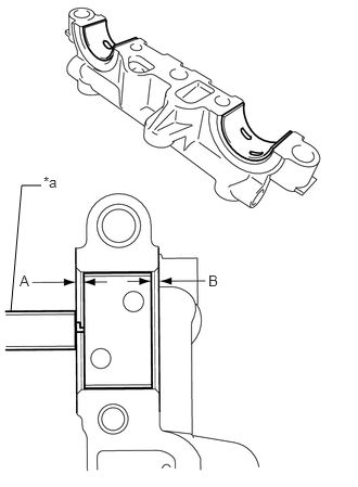
| *a | Vernier Caliper |
Using a vernier caliper, measure the distance between the camshaft bearing cap edge and the No. 1 camshaft bearing edge.
- Difference between (A) and (B):
0.7 mm (0.0276 in.) or less
- NOTICE:
-
Position the No. 1 camshaft bearings to the center of the camshaft bearing cap by measuring dimensions (A) and (B).
11821
2.INSTALL NO. 2 CAMSHAFT BEARING
Clean both surfaces of the 2 No. 2 camshaft bearings.
- NOTICE:
-
Do not apply engine oil to the No. 2 camshaft bearings or the contact surfaces.
Install the 2 No. 2 camshaft bearings to the camshaft housing sub-assembly.
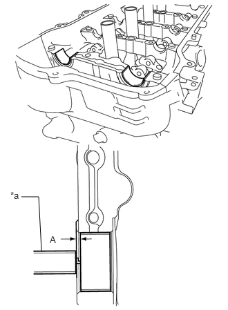
| *a | Vernier Caliper |
Using a vernier caliper, measure the distance between the camshaft housing sub-assembly edge and the No. 2 camshaft bearing edge.
- Dimension (A):
1.05 to 1.75 mm (0.0413 to 0.0689 in.)
- NOTICE:
-
Position the No. 2 camshaft bearings to the center of the camshaft housing sub-assembly by measuring dimension (A).
13050
3.INSTALL CAMSHAFT TIMING GEAR ASSEMBLY
Secure the hexagonal portion of the camshaft in a soft jaw vise.
Check that the straight pin is installed on the camshaft.
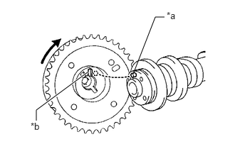
| *a | Straight Pin |
| *b | Key Groove |
Fit the camshaft timing gear assembly and camshaft together with the straight pin and key groove misaligned as shown in the illustration.
- NOTICE:
-
Do not forcibly push in the camshaft timing gear assembly. This may cause the straight pin tip to damage the installation surface of the camshaft timing gear assembly.
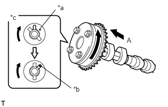
| *a | Straight Pin |
| *b | Key Groove |
| *c | View (A) |
Turn the camshaft timing gear assembly as shown in the illustration while pushing it gently against the camshaft. Push further at the position where the straight pin fits into the key groove.
- NOTICE:
-
Do not turn the camshaft timing gear assembly in the retard direction.
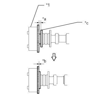
| *1 | Camshaft Timing Gear Assembly |
| *a | Gap |
| *b | No Gap |
| *c | Camshaft Flange |
Check that there is no gap between the camshaft timing gear assembly and camshaft flange.
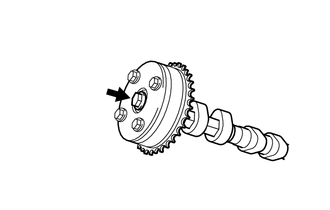
Tighten the bolt with the camshaft timing gear assembly secured in place.
- Torque:
- 54 N*m (551 kgf*cm, 40 ft.*lbf)
- NOTICE:
-
When tightening the bolt, do not allow the camshaft timing gear assembly to rotate.
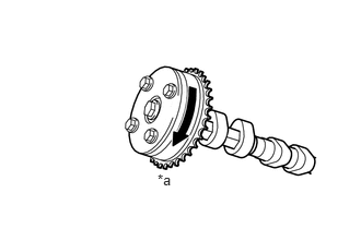
| *a | Lock |
Check that the camshaft timing gear assembly can move in the retard direction (clockwise) and locks in the most retarded position.
13511
4.INSTALL CAMSHAFT
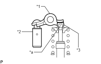
| *1 | No. 1 Valve Rocker Arm Sub-assembly |
| *2 | Valve Lash Adjuster Assembly |
| *3 | Valve Stem Cap |
| *a | Valve Stem |
Make sure that the No. 1 valve rocker arm sub-assembly is installed as shown in the illustration.
Clean the camshaft journals.
Apply a light coat of engine oil to the camshaft journals, camshaft housing sub-assembly and camshaft bearing caps.
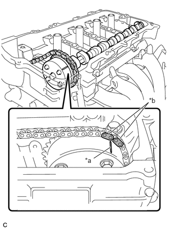
| *a | Timing Mark |
| *b | Paint Mark |
Hold up the chain sub-assembly, align the timing mark and paint mark and install the camshaft to the camshaft housing sub-assembly.
13512
5.INSTALL NO. 2 CAMSHAFT
| *1 | No. 1 Valve Rocker Arm Sub-assembly |
| *2 | Valve Lash Adjuster Assembly |
| *3 | Valve Stem Cap |
| *a | Valve Stem |
Make sure that the No. 1 valve rocker arm sub-assembly is installed as shown in the illustration.
Clean the No. 2 camshaft journals.
Apply a light coat of engine oil to the No. 2 camshaft journals and camshaft housing sub-assembly.
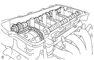
Install the No. 2 camshaft to the camshaft housing sub-assembly.
6.INSTALL CAMSHAFT BEARING CAP
Check the marks and numbers on the camshaft bearing caps, and then remove the service bolts and spacers in the order shown in the illustration. Immediately after removing the service bolts and spacers, install the camshaft bearing caps with the bolts in the order shown in the illustration.
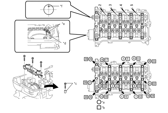
| *a | The Removal Order of the Service Bolts and Spacers for Temporarily Tightening the Camshaft Housing Sub-assembly | *b | The Installation Order of the Parts |
| *c | Service Bolt and Spacer (Used to Temporarily Secure the Camshaft Housing Sub-assembly) | *d | Timing Mark |
| *e | Paint Mark | *f | Straight Pin |
- Torque:
- 27 N*m (275 kgf*cm, 20 ft.*lbf)
- NOTICE:
-
If the bolts are loosened all at once, FIPG on the camshaft housing sub-assembly and cylinder head sub-assembly may peel off, resulting in oil oozing. Therefore, be sure to remove the service bolts and spacers from one camshaft bearing cap at a time.
- HINT:
-
Make sure that the orientation of the straight pin, timing mark and paint mark of the camshaft are as shown in the illustration.
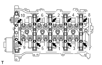
Tighten the 10 bolts in the order shown in the illustration.
- Torque:
- 16 N*m (163 kgf*cm, 12 ft.*lbf)
Check the torque of each bolt again.
13070A
7.INSTALL CAMSHAFT TIMING EXHAUST GEAR ASSEMBLY
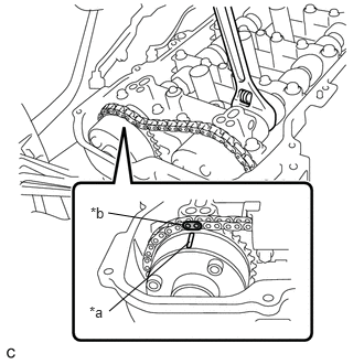
| *a | Timing Mark |
| *b | Paint Mark |
Hold the hexagonal portion of the camshaft with a wrench and turn the camshaft slightly counterclockwise to release the chain sub-assembly.
Insert the bolt into the camshaft timing exhaust gear assembly.
Align the paint mark with the timing mark to install the chain sub-assembly.
- NOTICE:
- ·
Do not turn the camshaft more than necessary.
·Do not install the camshaft timing exhaust gear assembly to the No. 2 camshaft in this step. Make sure to only install the chain sub-assembly to the camshaft timing exhaust gear assembly.
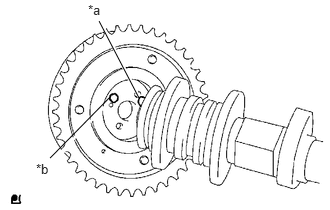
| *a | Straight Pin |
| *b | Pin Hole |
Fit the camshaft timing exhaust gear assembly and No. 2 camshaft together by aligning the pin hole and straight pin.
- NOTICE:
- ·
If the straight pin cannot be aligned with the pin hole, hold the hexagonal portion of the No. 2 camshaft with a wrench and turn it slightly to install the camshaft timing exhaust gear assembly.
·Do not turn the No. 2 camshaft more than necessary.
·Do not forcibly push in the camshaft timing exhaust gear assembly. This may cause the straight pin tip to damage the installation surface of the camshaft timing exhaust gear assembly.
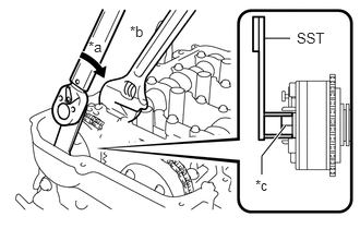
| *a | Turn |
| *b | Hold |
| *c | Bolt |
Using SST and a wrench, hold the hexagonal portion of the No. 2 camshaft and install the camshaft timing exhaust gear assembly to the No. 2 camshaft.
- SST
- 09249-37010
- Torque:
- without SST : 54 N*m (551 kgf*cm, 40 ft.*lbf)
- with SST : 39 N*m (398 kgf*cm, 29 ft.*lbf)
- NOTICE:
- ·
The "with SST" torque value can be obtained by using a torque wrench with a fulcrum length of 260 mm (10.2 in.) and SST of 100 mm (3.94 in.).
Click hereGeneral>INTRODUCTION>REPAIR INSTRUCTION>PRECAUTION
·This torque value is effective when SST is parallel to the torque wrench.
13562
8.INSTALL NO. 2 CHAIN VIBRATION DAMPER
Using SST, install the No. 2 chain vibration damper to the camshaft bearing cap with the 2 bolts.
- SST
- 09961-00950
- Torque:
- without SST : 10 N*m (102 kgf*cm, 7 ft.*lbf)
- with SST : 5.5 N*m (56 kgf*cm, 49 in.*lbf)
- NOTICE:
- ·
The "with SST" torque value can be obtained by using a torque wrench with a fulcrum length of 180 mm (7.09 in.) and SST of 150 mm (5.91 in.)
Click hereGeneral>INTRODUCTION>REPAIR INSTRUCTION>PRECAUTION
·This torque value is effective when SST is parallel to the torque wrench.
13540
9.INSTALL NO. 1 CHAIN TENSIONER ASSEMBLY
10.SET NO. 1 CYLINDER TO TDC/COMPRESSION
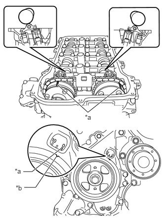
| *a | Timing Mark |
| *b | Timing Notch |
Turn the crankshaft pulley until its timing notch (groove) and the timing mark "0" of the timing chain cover sub-assembly are aligned.
Check that each timing mark of the camshaft timing gear assembly and camshaft timing exhaust gear assembly are aligned as shown in the illustration.
If not, turn the crankshaft 1 revolution (360°) to align the timing marks as shown in the illustration.
11213
11.INSTALL CYLINDER HEAD COVER GASKET
11201
12.INSTALL CYLINDER HEAD COVER SUB-ASSEMBLY
17361M
13.INSTALL AIR TUBE
Install the air tube with the 2 bolts.
- Torque:
- 10 N*m (102 kgf*cm, 7 ft.*lbf)
Connect the union to connector tube hose, No. 1 fuel vapor feed hose, No. 2 fuel vapor feed hose and No. 1 vacuum transmitting hose and slide the 3 clips to secure them.
82121
14.CONNECT ENGINE WIRE
Connect the engine wire with the 2 bolts.
- Torque:
- 8.4 N*m (86 kgf*cm, 74 in.*lbf)
Connect the 5 connectors and 5 clamps.
12262
15.CONNECT NO. 2 VENTILATION HOSE
Connect the No. 2 ventilation hose to the cylinder head cover sub-assembly and slide the clip to secure it.
19500
16.INSTALL IGNITION COIL ASSEMBLY
11212
17.INSTALL NO. 2 CYLINDER HEAD COVER
55701J
18.INSTALL OUTER COWL TOP PANEL SUB-ASSEMBLY