BRAKE SYSTEM (OTHER) BRAKE MASTER CYLINDER INSTALLATION
PROCEDURE

 1.INSPECT AND ADJUST BRAKE BOOSTER PUSH ROD
47201
2.INSTALL BRAKE MASTER CYLINDER SUB-ASSEMBLY
- NOTICE:
-
When installing a new brake master cylinder sub-assembly, remove the protectors from the master cylinder piston and outlet ports.
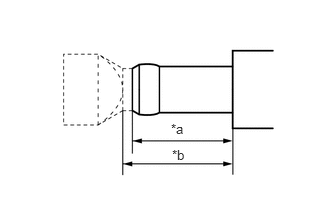
| *a | More than 22 mm (0.866 in.) |
| *b | 24 mm (0.945 in.) or less |
for Manual Transaxle:
When installing a new brake master cylinder reservoir assembly or a new brake master cylinder sub-assembly, cut off the clutch tube tip of the brake master cylinder reservoir assembly as shown in the illustration.
- CAUTION:
-
Be careful not to cut your finger on the cut surface.
- NOTICE:
- ·
Do not allow any foreign matter to enter the brake master cylinder reservoir assembly.
·Make sure that brake fluid supply is not affected by cutting the tube.
Install a new brake master cylinder O-ring to the brake master cylinder sub-assembly.
Install the brake master cylinder sub-assembly to the brake booster assembly with the 2 nuts.
- Torque:
- 12.5 N*m (127 kgf*cm, 9 ft.*lbf)
- NOTICE:
- ·
The brake master cylinder sub-assembly requires careful handling. Do not allow the brake master cylinder sub-assembly to receive any impact, such as from being dropped. Do not reuse a brake master cylinder sub-assembly that has been dropped.
·Do not hold the brake master cylinder sub-assembly by the master cylinder piston. Hold the brake master cylinder sub-assembly by its body or its reservoir when carrying it.
·Do not pull out the master cylinder piston.
·Do not strike or pinch the master cylinder piston, or cause any damage to the master cylinder piston by any other means.
·When installing the brake master cylinder sub-assembly to the brake booster assembly, or when removing the brake master cylinder sub-assembly from the brake booster assembly, make sure that the brake master cylinder sub-assembly is kept horizontal or with its tip facing downward (the master cylinder piston is facing upward) to prevent the master cylinder piston from falling out.
·Do not allow any foreign matter to contaminate the master cylinder piston. If any foreign matter gets on the master cylinder piston, remove it by using a piece of cloth and then apply an even layer of lithium soap base glycol grease around the circumference (sliding part) of the master cylinder piston.
·Do not kink or damage the brake lines.
·Do not allow the brake lines to twist or interfere with other parts or the vehicle body during tightening.
·Do not allow any foreign matter such as dirt or dust to enter the brake lines from the connecting parts.
·Do not use any other type of grease or fluid.
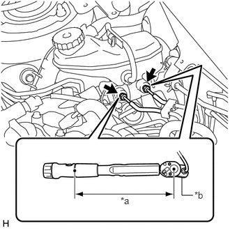
| *a | Torque Wrench Fulcrum Length |
| *b | Union Nut Wrench |
Using a union nut wrench, connect the 2 brake lines to the brake master cylinder sub-assembly.
- Torque:
- Specified tightening torque (w/o VSC) : 15.2 N*m (155 kgf*cm, 11 ft.*lbf)
- Specified tightening torque (w/ VSC) : 19.6 N*m (200 kgf*cm, 14 ft.*lbf)
- NOTICE:
- ·
Do not kink or damage the brake lines.
·Do not allow any foreign matter such as dirt or dust to enter the brake lines from the connecting parts.
- HINT:
- ·
Calculate the torque wrench reading when changing the fulcrum length of the torque wrench.
Click hereGeneral>INTRODUCTION>REPAIR INSTRUCTION>PRECAUTION
·When using a union nut wrench (fulcrum length of 22 mm (0.866 in.)) + torque wrench (fulcrum length of 162 mm (6.38 in.)):
w/o VSC: 13.38 N*m (136 kgf*cm, 10 ft.*lbf)
·When using a union nut wrench (fulcrum length of 20 mm (0.787 in.)) + torque wrench (fulcrum length of 162 mm (6.38 in.)):
w/ VSC: 17.45 N*m (178 kgf*cm, 13 ft.*lbf)
Connect the reservoir level switch connector and engage the clamp.
31434
3.CONNECT CLUTCH RESERVOIR TUBE (for Manual Transaxle)
Connect the clutch reservoir tube to the brake master cylinder sub-assembly and slide the clip to secure it.
4.BLEED BRAKE SYSTEM
5.BLEED CLUTCH LINE (for Manual Transaxle)
for C50: Click hereDrivetrain>CLUTCH>CLUTCH SYSTEM(for C50)>BLEEDING
for EC60: Click hereDrivetrain>CLUTCH>CLUTCH SYSTEM(for EC60)>BLEEDING
55701J
6.INSTALL OUTER COWL TOP PANEL SUB-ASSEMBLY
Install the outer cowl top panel sub-assembly with the 11 bolts.
- Torque:
- 12 N*m (122 kgf*cm, 9 ft.*lbf)
55737B
7.INSTALL NO. 1 HEATER AIR DUCT SPLASH SHIELD SEAL
Engage the clamp to install the No. 1 heater air duct splash shield seal.
55734A
8.INSTALL WATER GUARD PLATE RH
Engage the clamp to install the water guard plate RH.
9.INSTALL WINDSHIELD WIPER MOTOR AND LINK ASSEMBLY