U340E AUTOMATIC TRANSMISSION / TRANSAXLE AUTOMATIC TRANSAXLE UNIT REASSEMBLY
PROCEDURE

 1. BEARING POSITION
Check each bearing position and installation direction.
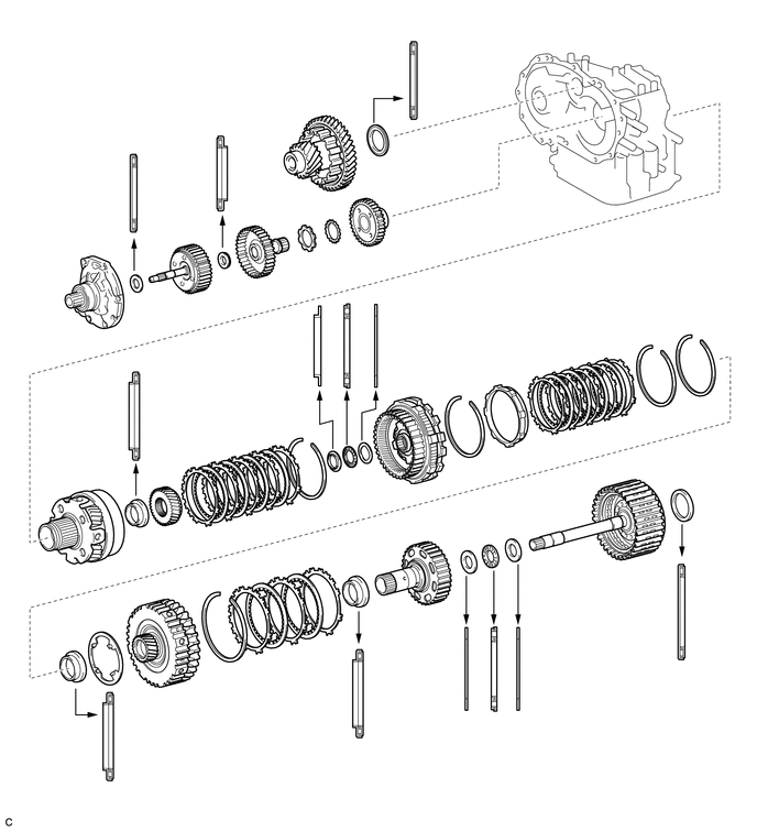
41311F
2.INSTALL FRONT DIFFERENTIAL CASE REAR TAPERED ROLLER BEARING
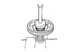
Using SST and a press, install a new front differential case rear tapered roller bearing (inner race) to the front differential case.
- SST
- 09726-40010
09950-60020 (09951-00790)
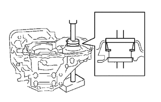
Using SST and a press, install a new front differential rear case shim and a new front differential case rear tapered roller bearing (outer race) to the transaxle case.
- SST
- 09950-60020 (09951-00720)
09950-60010 (09951-00650)
09950-70010 (09951-07100, 09951-07200)
41311E
3.INSTALL FRONT DIFFERENTIAL CASE FRONT TAPERED ROLLER BEARING
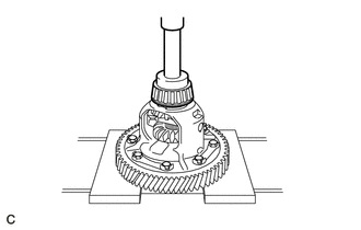
Using SST and a press, install a new front differential case front tapered roller bearing (inner race) to the front differential case.
- SST
- 09950-60010 (09951-00460)
09950-70010 (09951-07100)
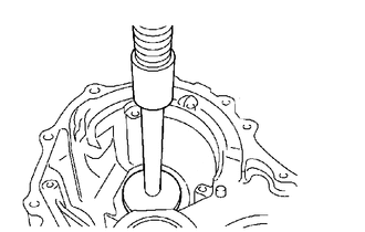
Using SST and a press, install a new front differential case front tapered roller bearing (outer race) to the transaxle housing.
- SST
- 09950-70010 (09951-07150)
09950-60020 (09951-00680)
4.INSPECT DIFFERENTIAL CASE TAPERED ROLLER BEARING PRELOAD
Remove any remaining seal packing from the contact surfaces of the transaxle housing and transaxle case.
Coat the differential gear assembly and bearings with ATF and install them to the transaxle case.
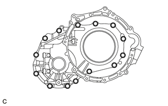
Install the transaxle housing to the transaxle case with the 14 bolts.
- Torque:
- Bolt (A) : 29.4 N*m (300 kgf*cm, 22 ft.*lbf)
- Bolt (B) : 22.1 N*m (225 kgf*cm, 16 ft.*lbf)
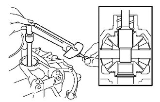
Using SST and a torque wrench, measure the preload of the differential gear assembly.
- SST
- 09564-32011
- Preload:
Bearing Standard New 0.98 to 1.57 N*m (10.0 to 16.0 kgf*cm, 8.7 to 13.9 in.*lbf) Used 0.49 to 0.78 N*m (5.0 to 8.0 kgf*cm, 4.3 to 6.9 in.*lbf)
If the preload is not as specified, replace the front differential rear case shim with one of a different thickness. Use the table below to select a front differential rear case shim which will ensure that the preload is within the specification.
- Front Differential Rear Case Shim Thickness:
Mark Thickness (mm (in.)) Mark Thickness (mm (in.)) 01 1.90 (0.0748) 11 2.40 (0.0945) 02 1.95 (0.0768) 12 2.45 (0.0965) 03 2.00 (0.0787) 13 2.50 (0.0984) 04 2.05 (0.0807) 14 2.55 (0.1004) 05 2.10 (0.0827) 15 2.60 (0.1024) 06 2.15 (0.0846) 16 2.65 (0.1043) 07 2.20 (0.0866) 17 2.70 (0.1063) 08 2.25 (0.0886) 18 2.75 (0.1083) 09 2.30 (0.0906) 19 2.80 (0.1102) 10 2.35 (0.0925) - -
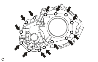
Remove the 14 bolts from the transaxle housing.
Remove the transaxle housing from the transaxle case.
Remove the differential gear assembly from the transaxle case.
43410M
5.INSTALL FRONT DRIVE SHAFT OIL SEAL RH
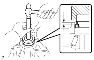
Coat the lip of a new front drive shaft oil seal RH with MP grease.
Using SST and a hammer, install the front drive shaft oil seal RH to the transaxle housing.
- SST
- 09554-14010
09950-70010 (09951-07100)
- Standard Depth:
1.5 to 2.5 mm (0.0591 to 0.0984 in.)
43420H
6.INSTALL FRONT DRIVE SHAFT OIL SEAL LH
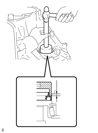
Coat the lip of a new front drive shaft oil seal LH with MP grease.
Using SST and a hammer, install the front drive shaft oil seal LH to the transaxle case.
- SST
- 09710-20011 (09710-06071)
09950-70010 (09951-07150)
- Standard Depth:
5.4 to 6.4 mm (0.213 to 0.251 in.)
41211B
7.INSTALL FRONT DRIVE PINION REAR CYLINDRICAL ROLLER BEARING
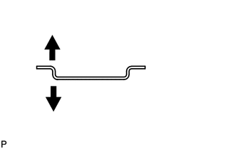
| *1 | No. 1 Transaxle Case Plate |
| *a | Front Drive Pinion Rear Cylindrical Roller Bearing Side |
| *b | Transaxle Case Side |
Install the No. 1 transaxle case plate to the transaxle case.
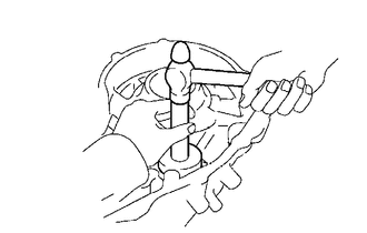
Using SST and a hammer, install a new front drive pinion rear cylindrical roller bearing to the transaxle case.
- SST
- 09950-60010 (09951-00610)
09950-70010 (09951-07150)
41211A
8.INSTALL FRONT DRIVE PINION FRONT CYLINDRICAL ROLLER BEARING
Install the front drive pinion thrust needle roller bearing RH to the transaxle housing.
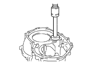
Using SST and a press, install a new front drive pinion front cylindrical roller bearing to the transaxle housing.
- SST
- 09950-60010 (09951-00650)
09950-70010 (09951-07150)
35882D
9.INSTALL DIFFERENTIAL GEAR LUBE APPLY TUBE
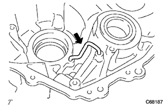
Install the differential gear lube apply tube to the transaxle housing.
33326E
10.INSTALL BEARING LOCK PLATE

Install the bearing lock plate to the transaxle housing with the bolt.
- Torque:
- 11.3 N*m (115 kgf*cm, 8 ft.*lbf)
35782D
11.INSTALL COUNTER DRIVE GEAR HOLE SNAP RING
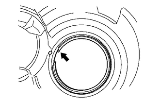
Using a screwdriver, install the counter drive gear hole snap ring to the transaxle case.
35782E
12.INSTALL COUNTER DRIVE GEAR BEARING LH
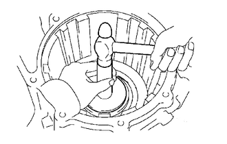
Using SST and a hammer, install a new counter drive gear bearing LH (outer race) to the transaxle case.
- SST
- 09950-60020 (09951-00890)
09950-70010 (09951-07150)
Install a new counter drive gear bearing LH (inner race) and a new angular ball to the transaxle case.
35782E
13.INSTALL COUNTER DRIVE GEAR BEARING RH
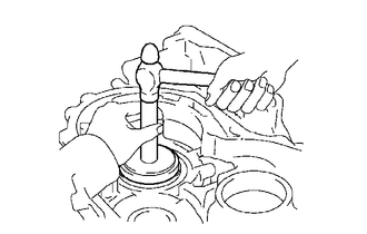
Using SST and a hammer, install a new counter drive gear bearing RH (outer race) to the transaxle case.
- SST
- 09950-60020 (09951-00890)
09950-70010 (09951-07150)
Install a new counter drive gear bearing RH (inner race) and a new angular ball to the transaxle case.
35506F
14.INSTALL MANUAL VALVE LEVER SHAFT OIL SEAL
Coat the lip of a new manual valve lever shaft oil seal with MP grease.
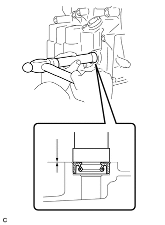
Using SST and a hammer, install the manual valve lever shaft oil seal to the transaxle case.
- SST
- 09950-60010 (09951-00220)
09950-70010 (09951-07100)
- Standard Depth:
-0.5 to 0.5 mm (-0.0197 to 0.0197 in.)
15.INSTALL DIFFERENTIAL DRIVE PINION
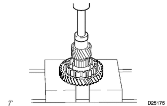
Using SST and a press, install the differential drive pinion to the counter driven gear.
- SST
- 09950-60010 (09951-00350)
09950-70010 (09951-07150)
- NOTICE:
-
When replacing the counter driven gear, replace the counter drive gear in the transaxle case as well.
-
Press in the differential drive pinion until it comes into contact with the counter driven gear.
41211E
16.INSTALL DIFFERENTIAL DRIVE PINION PLUG
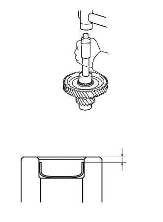
| *1 | Differential Drive Pinion Plug |
Using SST and a plastic hammer, install a new differential drive pinion plug to the differential drive pinion sub-assembly.
- SST
- 09221-25026 (09221-00071)
- Standard Clearance:
2.5 to 3.5 mm (0.0984 to 0.138 in.)
41205
17.INSTALL DIFFERENTIAL DRIVE PINION SUB-ASSEMBLY
Coat the drive pinion thrust bearing LH with ATF and install it to the transaxle case.
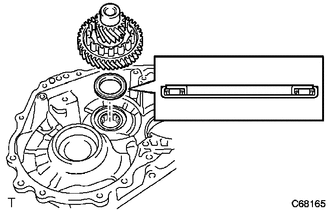
| *1 | Differential Drive Pinion Sub-assembly |
| *2 | Drive Pinion Thrust Bearing LH |
Install the differential drive pinion sub-assembly to the transaxle case.
35557
18.INSTALL PARKING LOCK PAWL
Coat the parking lock pawl shaft with ATF.
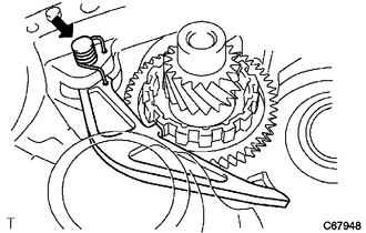
Install the parking lock pawl, parking lock pawl shaft torsion spring and parking lock pawl shaft to the transaxle case.
- NOTICE:
-
Check that the parking lock pawl moves smoothly.
35561
19.INSTALL MANUAL VALVE LEVER SHAFT
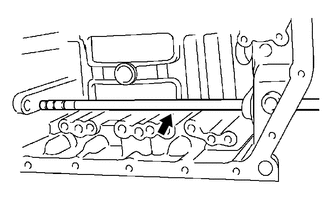
Install the manual valve lever shaft to the transaxle case.
- NOTICE:
-
Be careful not to damage the manual valve lever shaft oil seal lip.
35501
20.INSTALL PARKING LOCK ROD SUB-ASSEMBLY
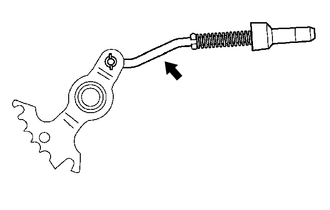
Install the parking lock rod sub-assembly to the manual valve lever sub-assembly.
35505
21.INSTALL MANUAL VALVE LEVER SUB-ASSEMBLY
Coat the manual valve lever sub-assembly with ATF.
Install the manual valve lever sub-assembly and a new manual valve lever spacer to the manual valve lever shaft.
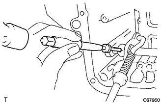
Using a 3 mm pin punch and a hammer, install the manual valve lever shaft slotted spring pin to the manual valve lever sub-assembly.
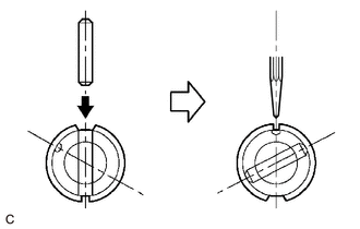
| *1 | Manual Valve Lever Shaft Slotted Spring Pin |
| *2 | Manual Valve Lever Spacer |
| *3 | Manual Valve Lever Sub-assembly |
| *4 | Manual Valve Lever Shaft |
| *a | Punch |
| *b | Staking Position Mark |
| *c | Small Hole |
Turn the manual valve lever spacer and manual valve lever sub-assembly to align the small hole for locating the staking position mark on the manual valve lever sub-assembly.
Using a punch, stake the manual valve lever spacer through the small hole.
Check that the manual valve lever spacer does not turn.
35506J
22.INSTALL MANUAL VALVE LEVER SHAFT RETAINER SPRING
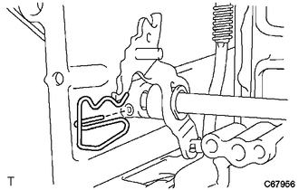
Install the manual valve lever shaft retainer spring to the manual valve lever shaft.
35595
23.INSTALL PARKING LOCK PAWL BRACKET
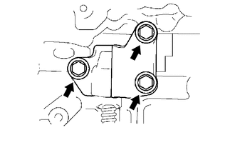
Install the parking lock pawl bracket and cam guide sleeve to the transaxle case with the 3 bolts.
- Torque:
- 20.1 N*m (205 kgf*cm, 15 ft.*lbf)
35623Q
24.INSTALL NO. 2 1ST AND REVERSE BRAKE PISTON O-RING
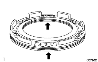
Coat 2 new No. 2 1st and reverse brake piston O-rings with ATF and install them to the No. 2 1st and reverse brake piston.
- NOTICE:
-
Be careful not to damage the No. 2 1st and reverse brake piston O-rings.
35623P
25.INSTALL NO. 2 1ST AND REVERSE BRAKE PISTON
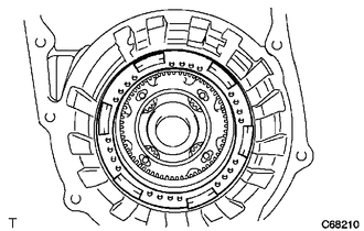
Coat the No. 2 1st and reverse brake piston with ATF and install it to the transaxle case.
- NOTICE:
-
Be careful not to damage the No. 2 1st and reverse brake piston O-rings.
35068
26.INSTALL 1ST AND REVERSE BRAKE RETURN SPRING SUB-ASSEMBLY
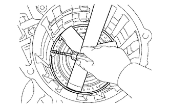
| *a | Protective Tape |
Install the 1st and reverse brake return spring sub-assembly to the transaxle case.
Place SST on the 1st and reverse brake return spring sub-assembly and compress the 1st and reverse brake return spring sub-assembly with a press.
- SST
- 09387-00070
- NOTICE:
-
Stop the press when the 1st and reverse brake return spring sub-assembly is flush with the snap ring groove. This prevents the 1st and reverse brake return spring sub-assembly from being deformed.
Using a screwdriver, install the snap ring to the transaxle case.
- NOTICE:
-
Be careful not to damage the transaxle case.
- HINT:
-
Tape the screwdriver tip before use.
35782C
27.INSTALL COUNTER DRIVE GEAR
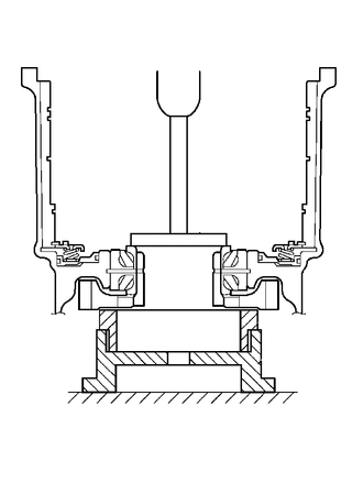
Using SST and a press, install the counter drive gear to the transaxle case.
- SST
- 09223-15030
09527-17011
09950-60010 (09951-00650)
09950-70010 (09951-07150)
35720G
28.INSTALL PLANETARY GEAR ASSEMBLY
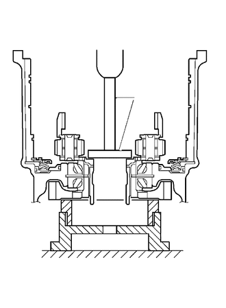
Using SST and a press, install the planetary gear assembly to the transaxle case.
- SST
- 09950-60010 (09951-00480)
09223-15030
09527-17011
09950-70010 (09951-07150)
35782H
29.INSTALL COUNTER DRIVE GEAR NUT
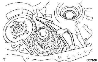
Secure the counter driven gear with the parking lock pawl.
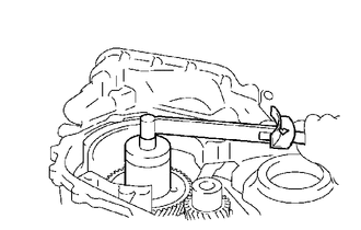
Using SST, install a new counter drive gear lock nut lock washer and counter drive gear nut.
- SST
- 09387-00121
- Torque:
- 280 N*m (2855 kgf*cm, 207 ft.*lbf)
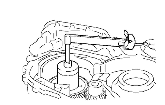
Using SST and a small torque wrench, measure the rotating torque while turning the counter drive gear at 60 rpm.
- SST
- 09387-00121
- Rotating Torque:
0.20 to 0.49 N*m (2.0 to 5.0 kgf*cm, 1.8 to 4.3 in.*lbf)
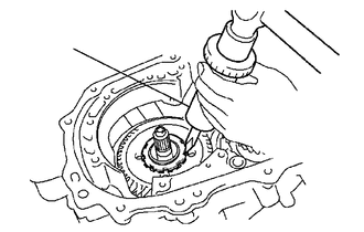
Using SST and a hammer, stake the counter drive gear lock nut lock washer.
- SST
- 09930-00010
35683
30.INSTALL 1ST AND REVERSE BRAKE DISC
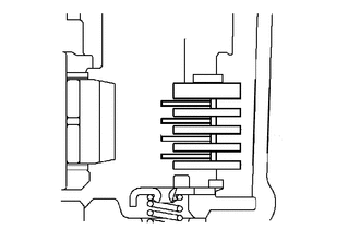
| *1 | 1st and Reverse Brake Disc |
| *2 | 1st and Reverse Brake Flange |
| *3 | 1st and Reverse Brake Plate |
Install the 4 1st and reverse brake plates, 4 1st and reverse brake discs and 1st and reverse brake flange to the transaxle case.
Using a screwdriver, install the snap ring to the transaxle case.
- NOTICE:
-
Be careful not to damage the transaxle case.
- HINT:
-
Tape the screwdriver tip before use.
31.INSPECT PACK CLEARANCE OF 1ST AND REVERSE BRAKE
35714D
32.INSTALL FRONT PLANETARY SUN GEAR
Coat the front planetary gear thrust needle roller bearing with ATF and install it to the planetary gear assembly.
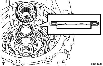
| *1 | Front Planetary Sun Gear |
| *2 | Front Planetary Gear Thrust Needle Roller Bearing |
Install the front planetary sun gear to the planetary gear assembly.
35664D
33.INSTALL 2ND BRAKE CYLINDER O-RING
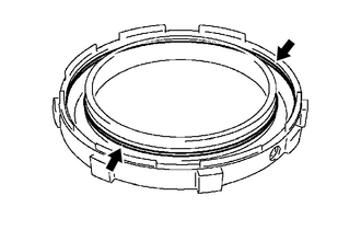
Coat 2 new 2nd brake cylinder O-rings with ATF and install them to the 2nd brake cylinder.
- NOTICE:
-
Be careful not to damage the 2nd brake cylinder O-rings.
35624E
34.INSTALL 2ND BRAKE PISTON
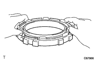
Coat the 2nd brake piston with ATF and install it to the 2nd brake cylinder.
- NOTICE:
-
Be careful not to damage the 2nd brake cylinder O-rings when pressing the 2nd brake piston to the 2nd brake cylinder by hand.
35608L
35.INSTALL 2ND BRAKE PISTON RETURN SPRING SUB-ASSEMBLY
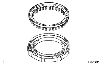
| *1 | 2nd Brake Piston Return Spring Sub-assembly |
| *2 | 2nd Brake Cylinder |
Install the 2nd brake piston return spring sub-assembly to the 2nd brake cylinder.
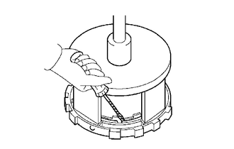
| *a | Protective Tape |
Place SST on the 2nd brake piston return spring sub-assembly and compress the 2nd brake piston return spring sub-assembly using a press.
- SST
- 09387-00060
Using a screwdriver, install the snap ring to the 2nd brake cylinder.
- NOTICE:
- ·
Stop the press when the 2nd brake piston return spring sub-assembly is flush with the snap ring groove. This prevents the 2nd brake piston return spring sub-assembly from being deformed.
·Be careful not to damage the 2nd brake cylinder.
·Make sure that the end gap of the snap ring is not aligned with the 2nd brake piston return spring sub-assembly claw.
- HINT:
-
Tape the screwdriver tip before use.
34365A
36.INSTALL OUTER RACE RETAINER
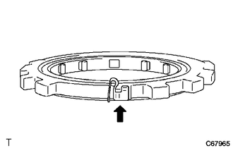
Install the outer race retainer to the No. 2 one-way clutch.
35792C
37.INSTALL NO. 2 ONE-WAY CLUTCH
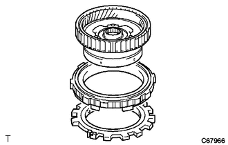
| *1 | Rear Planetary Gear Assembly |
| *2 | 2nd Brake Assembly |
| *3 | No. 2 One-way Clutch |
Install the No. 2 one-way clutch and 2nd brake assembly to the rear planetary gear assembly.
35786A
38.INSTALL NO. 1 THRUST BEARING RACE
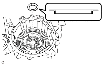
Coat the No. 1 thrust bearing race with ATF install it to the front planetary sun gear.
35720K
39.INSTALL REAR PLANETARY GEAR THRUST NEEDLE ROLLER BEARING
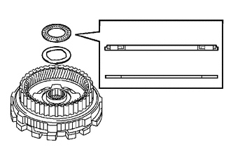
| *1 | Rear Planetary Gear Thrust Needle Roller Bearing |
| *2 | No. 2 Thrust Bearing Race |
Coat the No. 2 thrust bearing race and rear planetary gear thrust needle roller bearing with MP grease install them to the rear planetary gear assembly.
35760
40.INSTALL REAR PLANETARY GEAR ASSEMBLY
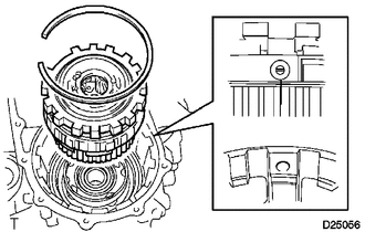
| *1 | Snap Ring |
| *2 | Rear Planetary Gear Assembly with No. 2 One-way Clutch and 2nd Brake Assembly |
Install the rear planetary gear assembly with No. 2 one-way clutch and 2nd brake assembly to the transaxle case.
Using a screwdriver, install the snap ring to the transaxle case.
- NOTICE:
-
Be careful not to damage the transaxle case.
- HINT:
-
Tape the screwdriver tip before use.
35792C
41.INSPECT NO. 2 ONE-WAY CLUTCH
35626D
42.INSTALL 2ND BRAKE PISTON SLEEVE
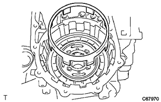
Install the 2nd brake piston sleeve to the transaxle case.
35682
43.INSTALL 2ND BRAKE DISC
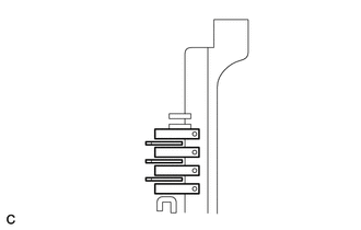
| *1 | 2nd Brake Disc |
| *2 | 2nd Brake Plate |
| *3 | 2nd Brake Flange |
| *4 | Snap Ring |
Install the 3 2nd brake discs, 2 2nd brake plates and 2 2nd brake flanges to the transaxle case.
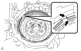
Using a screwdriver, install the 2 snap rings to the transaxle case as shown in the illustration.
- NOTICE:
-
Be careful not to damage the transaxle case.
- HINT:
-
Tape the screwdriver tip before use.
44.INSPECT PACK CLEARANCE OF 2ND BRAKE
35790A
45.INSTALL ONE-WAY CLUTCH ASSEMBLY
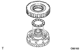
| *1 | One-way Clutch Assembly |
| *2 | No. 2 Planetary Carrier Thrust Washer |
Coat the No. 2 planetary carrier thrust washer with ATF and install it to the rear planetary sun gear assembly.
Install the one-way clutch assembly to the rear planetary sun gear assembly.
35790A
46.INSPECT ONE-WAY CLUTCH ASSEMBLY
35730
47.INSTALL REAR PLANETARY SUN GEAR ASSEMBLY
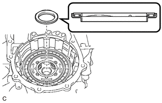
Coat the rear planetary sun gear thrust needle roller bearing with ATF and install it to the rear planetary gear assembly.
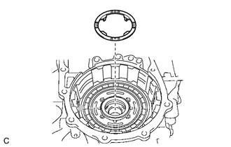
Coat the No. 1 planetary carrier thrust washer with ATF and install it to the rear planetary gear assembly.
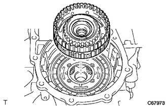
Install the rear planetary sun gear assembly with one-way clutch assembly to the transaxle case.
35730C
48.INSTALL REAR NO. 2 PLANETARY SUN GEAR THRUST NEEDLE ROLLER BEARING
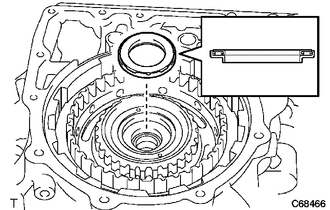
Coat the rear No. 2 planetary sun gear thrust needle roller bearing with ATF and install it to the rear planetary sun gear assembly.
35654B
49.INSTALL DIRECT CLUTCH HUB
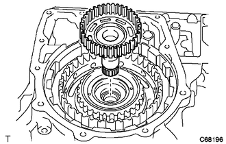
Install the direct clutch hub to the transaxle case.
35605B
50.INSTALL THRUST NEEDLE ROLLER BEARING
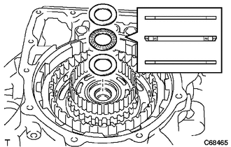
| *1 | C-2 Hub Thrust Bearing Race |
| *2 | Thrust Needle Roller Bearing |
| *3 | No. 3 Thrust Bearing Race |
Coat the No. 3 thrust bearing race, thrust needle roller bearing and C-2 hub thrust bearing race with ATF and install them to the direct clutch hub.
34633
51.INSTALL 2ND COAST AND OVERDRIVE BRAKE DISC
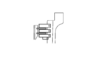
| *1 | 2nd Coast and Overdrive Brake Disc |
| *2 | 2nd Coast and Overdrive Brake Flange |
| *3 | No. 2 2nd Coast and Overdrive Brake Flange |
Install the 2 2nd coast and overdrive brake discs, 2 No. 2 2nd coast and overdrive brake flanges and 2nd coast and overdrive brake flange to the transaxle case.
35605D
52.INSTALL DIRECT CLUTCH DRUM O-RING
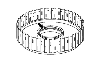
Coat a new direct clutch drum O-ring with ATF and install it to the direct clutch drum sub-assembly.
- NOTICE:
-
Be careful not to damage the direct clutch drum O-ring.
35605A
53.INSTALL DIRECT CLUTCH DRUM SUB-ASSEMBLY
Coat the direct clutch drum sub-assembly with ATF.
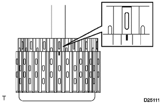
Align the cutout of the intermediate shaft sub-assembly with the matchmark on the direct clutch drum sub-assembly and install it to the intermediate shaft sub-assembly.
- NOTICE:
-
Be careful not to damage the direct clutch drum O-ring or the lip of the direct clutch drum sub-assembly.
35606C
54.INSTALL DIRECT CLUTCH PISTON O-RING
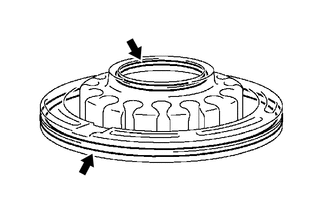
Coat 2 new direct clutch piston O-rings with ATF and install them to the direct clutch piston sub-assembly.
- NOTICE:
-
Be careful not to damage the direct clutch piston O-rings.
35606A
55.INSTALL DIRECT CLUTCH PISTON SUB-ASSEMBLY
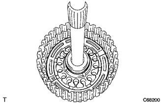
Coat the direct clutch piston sub-assembly with ATF and install it to the intermediate shaft sub-assembly.
- NOTICE:
-
Be careful not to damage the direct clutch piston O-rings or the direct clutch piston sub-assembly.
35604
56.INSTALL DIRECT CLUTCH RETURN SPRING SUB-ASSEMBLY
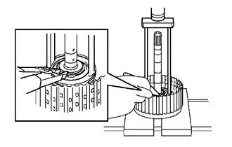
Install the direct clutch return spring sub-assembly to the intermediate shaft sub-assembly.
Place SST on the direct clutch return spring sub-assembly and compress the direct clutch return spring sub-assembly with a press.
- SST
- 09387-00020
- NOTICE:
-
Stop the press when the direct clutch return spring sub-assembly is flush with the snap ring groove. This prevents the direct clutch return spring sub-assembly from being deformed.
Using snap ring pliers, install the snap ring to the intermediate shaft sub-assembly.
- NOTICE:
-
Do not expand the snap ring excessively.
35667A
57.INSTALL DIRECT CLUTCH DISC
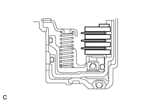
| *1 | Direct Clutch Flange |
| *2 | Snap Ring |
| *3 | Direct Clutch Disc |
| *4 | Rear Clutch Flange |
Coat the 3 rear clutch flanges, 3 direct clutch discs and direct clutch flange with ATF and install them to the intermediate shaft sub-assembly.
Using a screwdriver, install the snap ring to the intermediate shaft sub-assembly.
- NOTICE:
-
Be careful not to damage the intermediate shaft sub-assembly.
- HINT:
-
Tape the screwdriver tip before use.
35677H
58.INSTALL REVERSE CLUTCH DISC
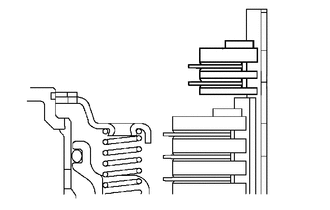
| *1 | Snap Ring |
| *2 | Reverse Clutch Flange |
| *3 | No. 3 Clutch Plate |
| *4 | Reverse Clutch Disc |
Install the 2 No. 3 clutch plates, 2 reverse clutch discs and reverse clutch flange to the intermediate shaft sub-assembly.
Using a screwdriver, install the snap ring to the intermediate shaft sub-assembly.
- NOTICE:
-
Be careful not to damage the intermediate shaft sub-assembly.
- HINT:
-
Tape the screwdriver tip before use.
35649
59.INSPECT PACK CLEARANCE OF REVERSE CLUTCH
60.INSPECT PACK CLEARANCE OF DIRECT CLUTCH
61.INSTALL INTERMEDIATE SHAFT ASSEMBLY
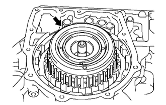
Install the intermediate shaft assembly to the transaxle case.
35102D
62.INSTALL REAR TRANSAXLE COVER NEEDLE ROLLER BEARING
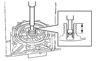
Coat a new rear transaxle cover needle roller bearing with ATF.
Using SST and a press, install the rear transaxle cover needle roller bearing to the rear transaxle cover sub-assembly.
- SST
- 09950-60010 (09951-00190, 09952-06010)
09950-70010 (09951-07100)
- Standard Clearance:
25.1 mm (0.988 in.)
35617G
63.INSTALL CLUTCH DRUM OIL SEAL RING
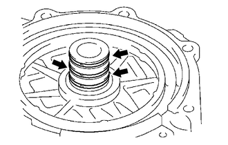
Coat the 3 new clutch drum oil seal rings with ATF and install them to the rear transaxle cover sub-assembly.
- NOTICE:
-
Do not expand the 3 clutch drum oil seal rings excessively.
34622C
64.INSTALL 2ND COAST AND OVERDRIVE O-RING
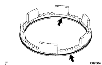
Coat 2 new 2nd coast and overdrive O-rings with ATF and install them to the 2nd coast and overdrive brake piston.
- NOTICE:
-
Be careful not to damage the 2nd coast and overdrive O-rings.
34622B
65.INSTALL 2ND COAST AND OVERDRIVE BRAKE PISTON
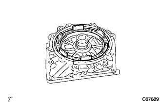
Coat the 2nd coast and overdrive brake piston with ATF and install it to the rear transaxle cover sub-assembly.
- NOTICE:
-
Be careful not to damage the 2nd coast and overdrive O-rings.
34603B
66.INSTALL OVERDRIVE BRAKE RETURN SPRING SUB-ASSEMBLY
Install the overdrive brake return spring sub-assembly to the 2nd coast and overdrive brake piston.
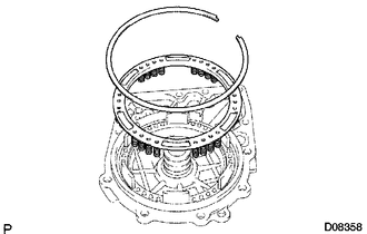
| *1 | Snap Ring |
| *2 | Overdrive Brake Return Spring Sub-assembly |
Place SST on the overdrive brake return spring sub-assembly and compress the overdrive brake return spring sub-assembly using a press.
- SST
- 09387-00070
- NOTICE:
-
Stop the press when the overdrive brake return spring sub-assembly is flush with the snap ring groove. This prevents the overdrive brake return spring sub-assembly from being deformed.
Using a screwdriver, install the snap ring to the rear transaxle cover sub-assembly.
- NOTICE:
-
Be careful not to damage the rear transaxle cover sub-assembly.
- HINT:
-
Tape the screwdriver tip before use.
67.INSPECT 2ND COAST AND OVERDRIVE BRAKE CLEARANCE
35651B
68.INSTALL REAR CLUTCH DRUM THRUST NEEDLE ROLLER BEARING
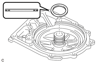
Coat the rear clutch drum thrust needle roller bearing with MP grease and install it to the rear transaxle cover sub-assembly.
69.INSPECT INTERMEDIATE SHAFT ASSEMBLY END PLAY
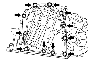
Install the rear transaxle cover sub-assembly to the transaxle case with the 11 bolts.
- Torque:
- 24.5 N*m (250 kgf*cm, 18 ft.*lbf)
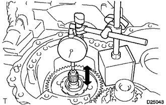
Using a dial indicator, measure the intermediate shaft assembly end play.
- End Play:
0.204 to 0.966 mm (0.00804 to 0.03803 in.)
If the end play is not as specified, replace the rear clutch drum thrust needle roller bearing with one of a different thickness.
- HINT:
-
There are 2 bearings of different thicknesses.
- Rear Clutch Drum Thrust Needle Roller Bearing:
Color Thickness (mm (in.)) Brown 3.551 mm (0.140 in.) Black 3.866 mm (0.152 in.)
Remove the 11 bolts from the rear transaxle cover sub-assembly.
35145C
70.INSTALL TRANSAXLE CASE O-RING
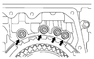
Coat 4 new transaxle case O-rings with ATF and install them to the transaxle case.
35102B
71.INSTALL REAR TRANSAXLE COVER PLUG
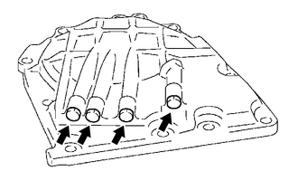
Coat 4 new O-rings with ATF and install them to the 4 rear transaxle cover plugs.
Install the 4 rear transaxle cover plugs to the rear transaxle cover sub-assembly.
- Torque:
- 7.4 N*m (75 kgf*cm, 65 in.*lbf)
- NOTICE:
-
Be careful not to damage the O-rings.
72.INSTALL REAR TRANSAXLE COVER ASSEMBLY
Remove any remaining seal packing (FIPG) from the contact surfaces of the rear transaxle cover assembly and transaxle case.
- NOTICE:
-
Make sure that there is no ATF on the contact surfaces.
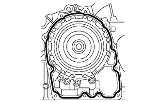
| *a | Seal Packing (FIPG)
(Seal Width: 1.2 mm (0.0472 in.)) |
Apply seal packing (FIPG) to the transaxle case.
- Seal Packing (FIPG):
Toyota Genuine Seal Packing 1281, Three Bond 1281 or equivalent
- NOTICE:
- ·
Install the parts within 10 minutes of application. Otherwise, the seal packing (FIPG) material must be removed and reapplied.
·Apply seal packing (FIPG) in a continuous line (width 1.2 mm (0.0472 in.)) a long the sealing surface of the transaxle case.
Install the rear transaxle cover assembly to the transaxle case with the 11 bolts.
- Torque:
- 24.5 N*m (250 kgf*cm, 18 ft.*lbf)
35061
73.INSTALL FORWARD CLUTCH HUB SUB-ASSEMBLY
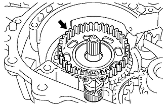
Install the forward clutch hub sub-assembly to the transaxle case.
35061C
74.INSTALL FORWARD CLUTCH HUB THRUST NEEDLE ROLLER BEARING
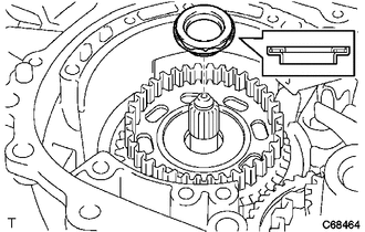
Coat the forward clutch hub thrust needle roller bearing with ATF and install it to the forward clutch hub sub-assembly.
35712A
75.INSTALL INPUT SHAFT OIL SEAL RING
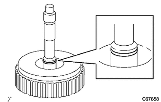
Coat a new input shaft oil seal ring with ATF and install it to the input shaft sub-assembly.
- NOTICE:
-
Be careful not to damage the input shaft oil seal ring.
35612C
76.INSTALL FORWARD CLUTCH PISTON O-RING
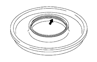
Coat a new forward clutch piston O-ring with ATF and install it to the forward clutch piston.
- NOTICE:
-
Be careful not to damage the forward clutch piston O-ring.
35612B
77.INSTALL FORWARD CLUTCH PISTON
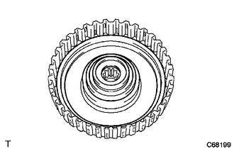
Coat the forward clutch piston with ATF and install it to the input shaft sub-assembly.
- NOTICE:
-
Be careful not to damage the forward clutch piston O-ring.
35603A
78.INSTALL FORWARD CLUTCH RETURN SPRING SUB-ASSEMBLY
Coat the lip seal of the No. 1 clutch balancer with ATF.
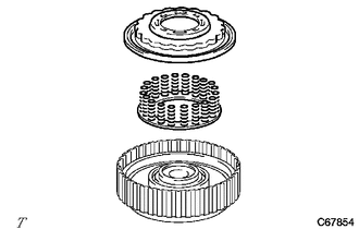
| *1 | No. 1 Clutch Balancer |
| *2 | Forward Clutch Return Spring Sub-assembly |
Install the forward clutch return spring sub-assembly and No. 1 clutch balancer to the input shaft sub-assembly.
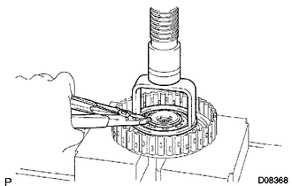
Place SST on the No. 1 clutch balancer and compress the forward clutch return spring sub-assembly using a press.
- SST
- 09320-89010
- NOTICE:
-
Stop the press when the forward clutch return spring sub-assembly is flush with the snap ring groove. This prevents the forward clutch return spring sub-assembly from being deformed.
Using snap ring pliers, install the snap ring to the input shaft sub-assembly.
- NOTICE:
-
Do not expand the snap ring excessively.
35633
79.INSTALL FRONT CLUTCH DISC
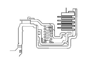
| *1 | Front Clutch Disc |
| *2 | Forward Clutch Flange |
| *3 | Forward Multiple Disc Clutch Plate |
Install the 4 forward multiple disc clutch plates, 4 front clutch discs and forward clutch flange to the input shaft sub-assembly.
Using a screwdriver, install the snap ring to the input shaft sub-assembly.
- NOTICE:
-
Be careful not to damage the input shaft sub-assembly.
- HINT:
-
Tape the screwdriver tip before use.
80.INSPECT PACK CLEARANCE OF FORWARD CLUTCH
35370A
81.INSTALL STATOR SHAFT THRUST NEEDLE ROLLER BEARING
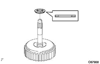
Coat the stator shaft thrust needle roller bearing with ATF and install it to the input shaft sub-assembly.
82.INSTALL INPUT SHAFT ASSEMBLY
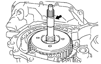
Install the input shaft assembly to the transaxle case.
83.INSTALL OVERDRIVE BRAKE O-RING
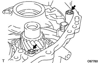
Coat 2 new overdrive brake O-rings with ATF and install them to the transaxle case.
84.INSTALL DIFFERENTIAL GEAR ASSEMBLY
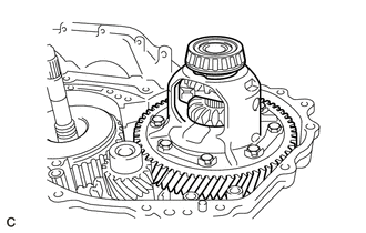
Install the differential gear assembly to the transaxle case.
85.INSTALL OIL PUMP ASSEMBLY
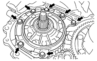
Install the oil pump assembly to the transaxle case with the 7 bolts.
- Torque:
- 22.1 N*m (225 kgf*cm, 16 ft.*lbf)
86.INSPECT INPUT SHAFT ASSEMBLY
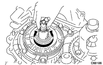
Make sure that the input shaft assembly turns smoothly.
87.INSPECT INPUT SHAFT ASSEMBLY END PLAY
35111C
88.INSTALL TRANSAXLE HOUSING
Remove any remaining seal packing (FIPG) from the contact surfaces of the transaxle housing and transaxle case.
- NOTICE:
-
Make sure that there is no ATF on the contact surfaces.
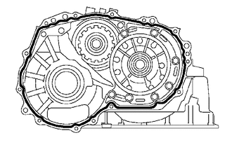
| *a | Seal Packing (FIPG)
(Seal Width: 1.2 mm (0.0472 in.)) |
Apply seal packing (FIPG) to the transaxle case.
- Seal Packing (FIPG):
Toyota Genuine Seal Packing 1281, Three Bond 1281 or equivalent
- NOTICE:
- ·
Install the parts within 10 minutes of application. Otherwise, the seal packing (FIPG) material must be removed and reapplied.
·Apply seal packing (FIPG) in a continuous line (width 1.2 mm (0.0472 in.)) a long the sealing surface of the transaxle case.
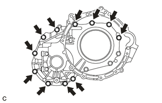
Temporarily install the transaxle housing to the transaxle case with the 11 bolts.
- Torque:
- 29.4 N*m (300 kgf*cm, 22 ft.*lbf)
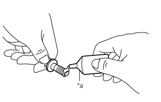
| *a | Adhesive |
Clean and degrease the 3 bolts and the installation holes in the transaxle case.
Apply adhesive to 2 or 3 threads on the ends of the 3 bolts.
- Adhesive:
Toyota Genuine Adhesive 1324, Three Bond 1324 or equivalent
- NOTICE:
-
In order to ensure proper installation of the 3 bolts, apply adhesive to the 3 bolts and install them within 10 minutes of adhesive application.
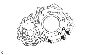
Install the 3 bolts.
- Torque:
- 22.1 N*m (225 kgf*cm, 16 ft.*lbf)
35425A
89.INSTALL C-2 ACCUMULATOR PISTON
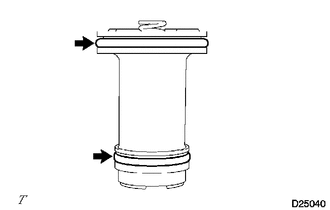
Coat 2 new C-2 accumulator piston O-rings with ATF and install them to the C-2 accumulator piston.
- NOTICE:
-
Be careful not to damage the C-2 accumulator piston O-rings.

Install the C-2 accumulator piston compression spring and C-2 accumulator piston to the transaxle case.
- C-2 Accumulator Piston Compression Spring:
Spring Free Length
(mm (in.))Color C-2 66.90 mm (2.63 in.) -
35426D
90.INSTALL C-3 ACCUMULATOR PISTON
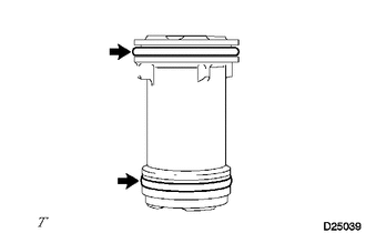
Coat 2 new C-3 accumulator piston O-rings with ATF and install them to the C-3 accumulator piston.
- NOTICE:
-
Be careful not to damage the C-3 accumulator piston O-rings.
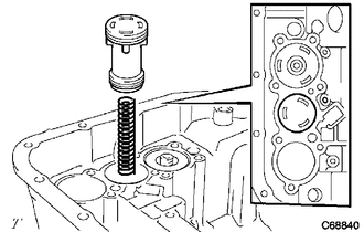
Install the C-3 accumulator piston compression spring and C-3 accumulator piston to the transaxle case.
- C-3 Accumulator Piston Compression Spring:
Spring Free Length
(mm (in.))Color C-3 80.20 mm (3.16 in.) Blue
35423
91.INSTALL B-2 ACCUMULATOR PISTON
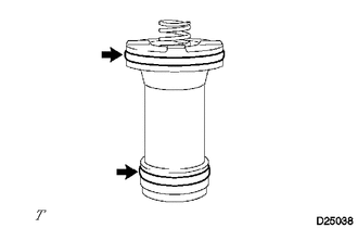
Coat 2 new B-2 accumulator piston O-rings with ATF and install them to the B-2 accumulator piston.
- NOTICE:
-
Be careful not to damage the B-2 accumulator piston O-rings.
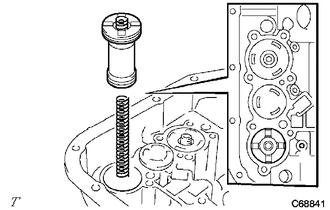
Install the B-2 accumulator piston compression spring and B-2 accumulator piston to the transaxle case.
- B-2 Accumulator Piston Compression Spring:
Spring Free Length
(mm (in.))Color B-2 66.90 mm (2.63 in.) Green
35251
92.INSTALL CHECK BALL BODY
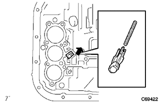
Install the check ball body compression spring and check ball body to the transaxle case.
35159
93.INSTALL BRAKE DRUM GASKET
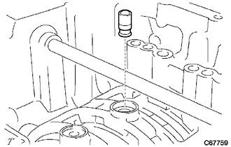
Coat a new brake drum gasket with ATF and install it to the transaxle case.
- NOTICE:
-
Be careful not to damage the brake drum gasket.
35149B
94.INSTALL TRANSAXLE CASE 2ND BRAKE GASKET
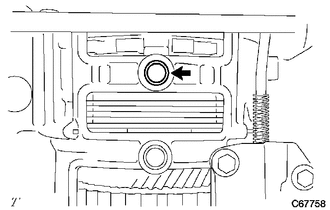
Coat a new transaxle case 2nd brake gasket with ATF and install it to the transaxle case.
- NOTICE:
-
Be careful not to damage the transaxle case 2nd brake gasket.
35145C
95.INSTALL TRANSAXLE CASE GASKET
Coat a new transaxle case gasket with ATF and install it to the transaxle case.
- NOTICE:
-
Be careful not to damage the transaxle case gasket.
82125J
96.INSTALL TRANSMISSION WIRE
35410
97.INSTALL TRANSMISSION VALVE BODY ASSEMBLY
35330
98.INSTALL VALVE BODY OIL STRAINER ASSEMBLY
35394
99.INSTALL TRANSMISSION OIL CLEANER MAGNET
35106D
100.INSTALL AUTOMATIC TRANSAXLE OIL PAN SUB-ASSEMBLY
101.INSTALL DRAIN PLUG
Using a 10 mm hexagon socket wrench, install the drain plug and a new gasket to the automatic transaxle oil pan sub-assembly.
35104B
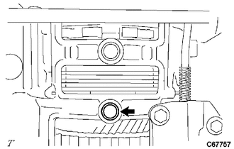
102.INSTALL BREATHER PLUG
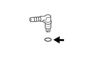
Coat a new O-ring with ATF and install it to the breather plug.
- NOTICE:
-
Be careful not to damage the O-ring.
Install the breather plug to the transaxle case.
35104V
103.INSTALL BREATHER PLUG HOSE
Install the No. 1 breather plug (ATM) to the breather plug hose.
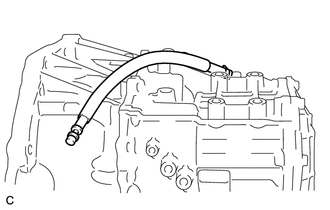
Install the breather plug hose to the breather plug.
35104Q
104.INSTALL NO. 1 TRANSAXLE CASE PLUG
Coat 4 new O-rings with ATF and install them to the 4 No. 1 transaxle case plugs.
- NOTICE:
-
Be careful not to damage the O-rings.
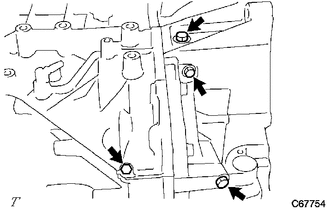
Install the 4 No. 1 transaxle case plugs to the transaxle housing and transaxle case.
- Torque:
- 7.4 N*m (75 kgf*cm, 65 in.*lbf)
Coat a new O-ring with ATF and install it to the No. 1 transaxle case plug.
- NOTICE:
-
Be careful not to damage the O-ring.
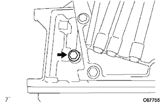
Install the No. 1 transaxle case plug to the transaxle case.
- Torque:
- 7.4 N*m (75 kgf*cm, 65 in.*lbf)
32921C
105.INSTALL OIL COOLER TUBE UNION
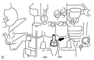
for Straight Type:
Coat a new O-ring with ATF and install it to the oil cooler tube union.
- NOTICE:
-
Be careful not to damage the O-ring.
Install the oil cooler tube union to the transaxle case.
- Torque:
- 27 N*m (275 kgf*cm, 20 ft.*lbf)
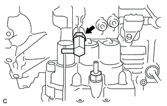
for Elbow Type:
Coat a new O-ring with ATF and install it to the oil cooler tube union.
- NOTICE:
-
Be careful not to damage the O-ring.
Install the oil cooler tube union to the transaxle case as shown in the illustration.
- Torque:
- 27 N*m (275 kgf*cm, 20 ft.*lbf)
89413B
106.INSTALL TRANSMISSION REVOLUTION SENSOR
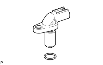
Coat a new O-ring with ATF and install it to the transmission revolution sensor.
- NOTICE:
-
Be careful not to damage the O-ring.
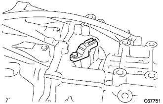
Install the transmission revolution sensor to the automatic transaxle assembly with the bolt.
- Torque:
- 7.8 N*m (80 kgf*cm, 69 in.*lbf)
84540
107.INSTALL PARK/NEUTRAL POSITION SWITCH ASSEMBLY
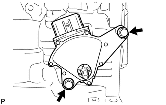
Temporarily install the park/neutral position switch assembly to the transaxle case with the 2 bolts.
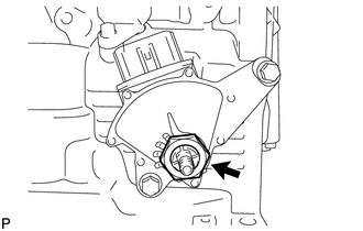
Install the lock plate and lock nut to the park/neutral position switch assembly.
- Torque:
- 6.9 N*m (70 kgf*cm, 61 in.*lbf)
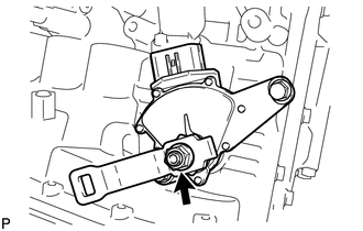
Temporarily install the control shaft lever to the manual valve lever shaft with the nut and washer.
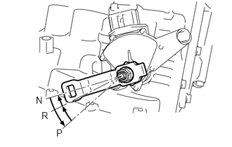
Turn the control shaft lever counterclockwise until it stops, then turn it clockwise 2 notches.
Remove the nut, washer and control shaft lever from the manual valve lever shaft.
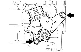
| *a | Neutral Basic Line |
| *b | Indicator |
Align the indicator with the neutral basic line.
Hold the park/neutral position switch assembly in position and tighten the 2 bolts.
- Torque:
- 5.4 N*m (55 kgf*cm, 48 in.*lbf)
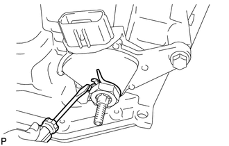
Using a screwdriver, stake the lock nut with the lock plate.
Install the control shaft lever to the manual valve lever shaft with the nut and washer.
- Torque:
- 12.7 N*m (130 kgf*cm, 9 ft.*lbf)