U340E AUTOMATIC TRANSMISSION / TRANSAXLE AUTOMATIC TRANSAXLE UNIT INSPECTION
PROCEDURE

 35633
1.INSPECT FRONT CLUTCH DISC
35633
1.INSPECT FRONT CLUTCH DISC
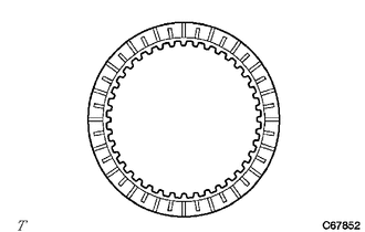
Check if the contact surfaces of the 4 front clutch discs, 4 forward multiple disc clutch plates and forward clutch flange are worn or burnt.
If necessary, replace them.
- NOTICE:
- ·
If the lining of any of the front clutch discs is peeled off or discolored, or even if part of the printed mark is damaged, replace all the front clutch discs.
·Before installing new front clutch discs, soak them in ATF for at least 15 minutes.
35603A
2.INSPECT FORWARD CLUTCH RETURN SPRING SUB-ASSEMBLY
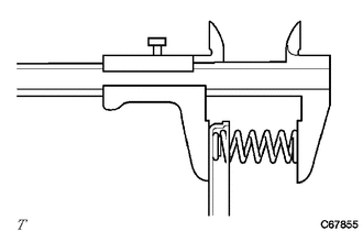
Using a vernier caliper, measure the free length of the forward clutch return spring sub-assembly together with the spring seat.
- Standard Free Length:
21.69 mm (0.854 in.)
If the free length is shorter than the standard free length, replace the forward clutch return spring sub-assembly.
34603B
3.INSPECT OVERDRIVE BRAKE RETURN SPRING SUB-ASSEMBLY
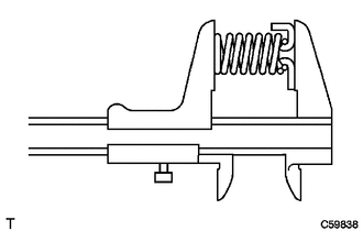
Using a vernier caliper, measure the free length of the overdrive brake return spring sub-assembly together with the spring seat.
- Standard Free Length:
17.88 mm (0.704 in.)
If the free length is shorter than the standard free length, replace the overdrive brake return spring sub-assembly.
35677H
4.INSPECT REVERSE CLUTCH DISC
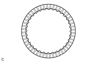
Check if the contact surfaces of the 2 reverse clutch discs, 2 No. 3 clutch plates and reverse clutch flange are worn or burnt.
If necessary, replace them.
- NOTICE:
- ·
If the lining of any of the reverse clutch discs is peeled off or discolored, or even if part of the printed mark is damaged, replace all the reverse clutch discs.
·Before installing new reverse clutch discs, soak them in ATF for at least 15 minutes.
35667A
5.INSPECT DIRECT CLUTCH DISK
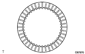
Check if the contact surfaces of the 3 direct clutch discs, 3 rear clutch flanges and direct clutch flange are worn or burnt.
If necessary, replace them.
- NOTICE:
- ·
If the lining of any of the direct clutch discs is peeled off or discolored, or even if part of the printed mark is damaged, replace all the direct clutch discs.
·Before installing new direct clutch discs, soak them in ATF for at least 15 minutes.
35604
6.INSPECT DIRECT CLUTCH RETURN SPRING SUB-ASSEMBLY
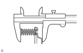
Using a vernier caliper, measure the free length of the direct clutch return spring sub-assembly together with the spring seat.
- Standard Free Length:
38.5 mm (1.516 in.)
If the free length is shorter than the standard free length, replace the direct clutch return spring sub-assembly.
35606A
7.INSPECT DIRECT CLUTCH PISTON SUB-ASSEMBLY
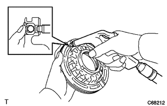
Shake the direct clutch pin and confirm that the check ball is not stuck.
Apply low pressure compressed air to the check ball and confirm that there are no air leaks.
35708G
8.INSPECT INTERMEDIATE SHAFT SUB-ASSEMBLY
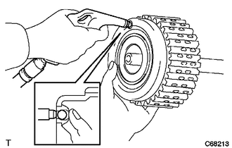
Shake the direct clutch pin and confirm that the check ball is not stuck.
Apply low pressure compressed air to the check ball and confirm that there are no air leaks.
34633
9.INSPECT 2ND COAST AND OVERDRIVE BRAKE DISC
Check if the contact surfaces of the 2 2nd coast and overdrive brake discs, 2 No. 2 2nd coast and overdrive brake flanges and 2nd coast and overdrive brake flange are worn or burnt.
If necessary, replace them.
- NOTICE:
- ·
If the lining of any of the 2nd coast and overdrive brake discs is peeled off or discolored, or even if part of the printed mark is damaged, replace all the 2nd coast and overdrive brake discs.
·Before installing new 2nd coast and overdrive brake discs, soak them in ATF for at least 15 minutes.
35682
10.INSPECT 2ND BRAKE DISC
Check if the contact surfaces of the 3 2nd brake discs, 2 2nd brake plates and 2 2nd brake flanges are worn or burnt.
If necessary, replace them.
- NOTICE:
- ·
If the lining of any of the 2nd brake discs is peeled off or discolored, or even if part of the printed mark is damaged, replace all the 2nd brake discs.
·Before installing new 2nd brake discs, soak them in ATF for at least 15 minutes.
35608L
11.INSPECT 2ND BRAKE PISTON RETURN SPRING SUB-ASSEMBLY
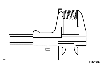
Using a vernier caliper, measure the free length of the 2nd brake piston return spring sub-assembly including the spring seat.
- Standard Free Length:
14.65 mm (0.577 in.)
If the free length is shorter than the standard free length, replace the 2nd brake piston return spring sub-assembly.
35683
12.INSPECT 1ST AND REVERSE BRAKE DISC
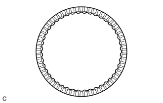
Check if the contact surfaces of the 4 1st and reverse brake discs, 4 1st and reverse brake plates and 1st and reverse brake flange are worn or burnt.
If necessary, replace them.
- NOTICE:
- ·
If the lining of any of the 1st and reverse brake discs is peeled off or discolored, or even if part of the printed mark is damaged, replace all the 1st and reverse brake discs.
·Before installing new 1st and reverse brake discs, soak them in ATF for at least 15 minutes.
35068
13.INSPECT 1ST AND REVERSE BRAKE RETURN SPRING SUB-ASSEMBLY
Using a vernier caliper, measure the free length of the 1st and reverse brake return spring sub-assembly together with the spring seat.
- Standard Free Length:
13.96 mm (0.550 in.)
If the free length is shorter than the standard free length, replace the 1st and reverse brake return spring sub-assembly.
14.INSPECT INPUT SHAFT ASSEMBLY END PLAY
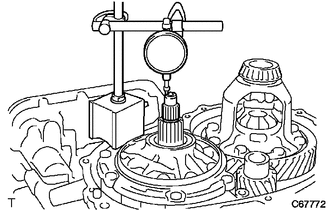
Using a dial indicator, measure the input shaft assembly end play.
- End Play:
0.374 to 1.292 mm (0.0147 to 0.0509 in.)
If the end play is not as specified, replace the stator shaft thrust needle roller bearing and forward clutch hub thrust needle roller bearing.
15.INSPECT INTERMEDIATE SHAFT ASSEMBLY END PLAY
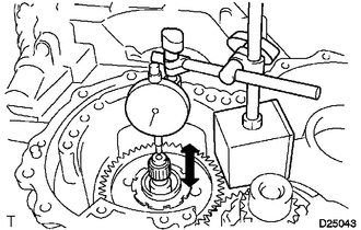
Using a dial indicator, measure the intermediate shaft assembly end play.
- End Play:
0.204 to 0.966 mm (0.00803 to 0.03803 in.)
If the end play is not as specified, replace the rear clutch drum thrust needle roller bearing with one of a different thickness.
- HINT:
-
There are 2 bearings of different thicknesses.
- Rear Clutch Drum Thrust Needle Roller Bearing:
Color Thickness (mm (in.)) Brown 3.551 mm (0.140 in.) Black 3.866 mm (0.152 in.)
35790A
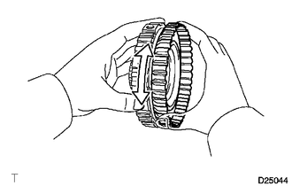
16.INSPECT ONE-WAY CLUTCH ASSEMBLY
| *a | Hold |
| *b | Free |
| *c | Locks |
While holding the rear planetary sun gear assembly by hand, turn the one-way clutch assembly and check that the one-way clutch assembly turns freely counterclockwise and locks when turned clockwise.
If the one-way clutch assembly does not operate as specified, replace it.
35792C
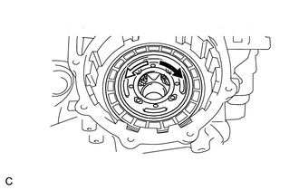
17.INSPECT NO. 2 ONE-WAY CLUTCH
| *1 | Rear Planetary Gear Assembly |
| *a | Locks |
| *b | Free |
Check that the rear planetary gear assembly turns freely counterclockwise and locks when turned clockwise.
If the No. 2 one-way clutch does not operate as specified, replace it.
18.INSPECT PACK CLEARANCE OF 1ST AND REVERSE BRAKE
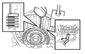
Using SST and a dial indicator, measure the 1st and reverse brake clearance while pressing the 1st and reverse brake discs and 1st and reverse brake plates from the rear side.
- SST
- 09350-36010 (09350-06110)
- Pack Clearance:
0.806 to 1.206 mm (0.0317 to 0.0475 in.)
- NOTICE:
-
If the clearance is not as specified, select an appropriate new 1st and reverse brake flange so that the clearance will be within the specified range.
- HINT:
-
There are 4 1st and reverse brake flanges of different thicknesses.
- 1st and Reverse Brake Flange Thickness:
Mark Thickness (mm (in.)) Mark Thickness (mm (in.)) - 3.4 (0.134) 2 3.8 (0.150) 1 3.6 (0.142) 3 4.0 (0.157)
Check that the 1st and reverse brake piston moves when compressed air (392 kPa, 4.0 kgf/cm2, 57 psi) is applied to the oil hole.
19.INSPECT PACK CLEARANCE OF 2ND BRAKE
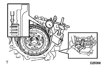
Using a dial indicator, measure the 2nd brake pack clearance while applying and releasing compressed air (392 to 785 kPa, 4.0 to 8.0 kgf/cm2, 57 to 114 psi).
- Pack Clearance:
0.847 to 1.247 mm (0.0333 to 0.0491 in.)
- NOTICE:
-
If the clearance is not as specified, select an appropriate new 2nd brake flange so that the clearance will be within the specified range.
- HINT:
-
There are 4 2nd brake flanges of different thicknesses.
- 2nd Brake Flange Thickness:
Mark Thickness (mm (in.)) Mark Thickness (mm (in.)) - 3.0 (0.118) 2 3.4 (0.134) 1 3.2 (0.126) 3 3.6 (0.142)
35649
20.INSPECT PACK CLEARANCE OF REVERSE CLUTCH
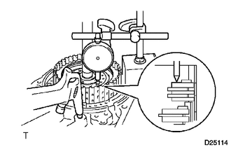
Install the intermediate shaft assembly and rear clutch drum thrust needle roller bearing to the rear transaxle cover assembly.
Using a dial indicator, measure the reverse clutch pack clearance while applying and releasing compressed air (392 kPa, 4.0 kgf/cm2, 57 psi).
- HINT:
-
The direct and reverse clutch will move as compressed air is applied.
-
Therefore, while performing the check, press on the intermediate shaft assembly using a press or equivalent.
- Pack Clearance:
0.862 to 1.262 mm (0.0340 to 0.0496 in.)
- NOTICE:
-
If the clearance is not as specified, select an appropriate new reverse clutch flange so that the clearance will be within the specified range.
- HINT:
-
There are 4 reverse clutch flanges of different thicknesses.
- Reverse Clutch Flange Thickness:
Mark Thickness (mm (in.)) Mark Thickness (mm (in.)) - 3.0 (0.118) 2 3.4 (0.134) 1 3.2 (0.126) 3 3.6 (0.142)
21.INSPECT PACK CLEARANCE OF DIRECT CLUTCH
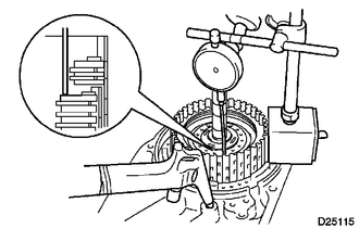
Install the intermediate shaft assembly and thrust needle roller bearing to the rear transaxle cover assembly.
Using a dial indicator and measuring terminal (SST), measure the direct clutch pack clearance while applying and releasing compressed air (392 kPa, 4.0 kgf/cm2, 57 psi).
- SST
- 09350-36010 (09350-06110)
- HINT:
-
The direct and reverse clutch will move as compressed air is applied.
-
Therefore, while performing the check, press on the intermediate shaft assembly using a press or equivalent.
- Pack Clearance:
0.62 to 1.02 mm (0.0244 to 0.0402 in.)
- NOTICE:
-
If the clearance is not as specified, select an appropriate new direct clutch flange so that the clearance will be within the specified range.
- HINT:
-
There are 4 direct clutch flanges of different thicknesses.
- Direct Clutch Flange Thickness:
Mark Thickness (mm (in.)) Mark Thickness (mm (in.)) - 3.0 (0.118) 2 3.4 (0.134) 1 3.2 (0.126) 3 3.6 (0.142)
22.INSPECT 2ND COAST AND OVERDRIVE BRAKE CLEARANCE
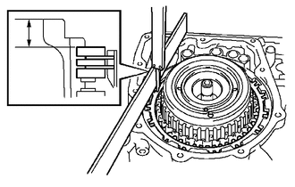
As shown in the illustration, place a straightedge on the transaxle case and measure the distance between the 2nd coast and overdrive brake flange and the straightedge using a vernier caliper. (Dimension B)
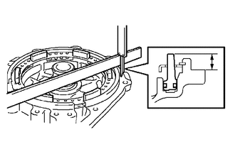
As shown in the illustration, place a straightedge on the 2nd coast and overdrive brake piston and measure the distance between the rear transaxle cover assembly and straightedge using a vernier caliper. (Dimension C)
Calculate the piston stroke value using the following formula.
- Formula:
Dimension B - Dimension C
- Pack Clearance:
2.091 to 2.491 mm (0.0823 to 0.0981 in.)
- NOTICE:
-
If the clearance is not as specified, select an appropriate new 2nd coast and overdrive brake flange so that the clearance will be within the specified range.
- HINT:
-
There are 4 2nd coast and overdrive brake flanges of different thicknesses.
- 2nd Coast and Overdrive Brake Flange Thickness:
Mark Thickness (mm (in.)) Mark Thickness (mm (in.)) 4 4.0 (0.1575) 6 4.4 (0.1732) 5 4.2 (0.1654) 7 4.6 (0.1811)
23.INSPECT PACK CLEARANCE OF FORWARD CLUTCH
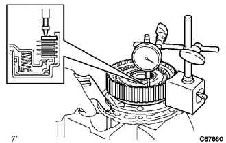
Using a dial indicator, measure the pack clearance while applying and releasing compressed air (392 kPa, 4.0 kgf/cm2, 57 psi).
- Pack Clearance:
1.406 to 1.806 mm (0.0554 to 0.0711 in.)
- NOTICE:
-
If the clearance is not as specified, select an appropriate new forward clutch flange so that the clearance will be within the specified range.
- HINT:
-
There are 4 forward clutch flanges of different thicknesses.
- Forward Clutch Flange Thickness:
Mark Thickness (mm (in.)) Mark Thickness (mm (in.)) - 3.0 (0.118) 2 3.4 (0.134) 1 3.2 (0.126) 3 3.6 (0.142)