EC60 MANUAL TRANSMISSION / TRANSAXLE MANUAL TRANSAXLE ASSEMBLY INSTALLATION
CAUTION / NOTICE / HINT
- CAUTION:
-
The engine assembly with manual transaxle assembly is very heavy. Be sure to follow the procedure described in the repair manual, or the engine lifter may suddenly drop.
- NOTICE:
-
When the manual transaxle assembly is removed, be sure to use a new clutch release with bearing cylinder assembly and new installation bolts. Removal of the manual transaxle assembly allows the compressed clutch release with bearing cylinder assembly to return to its original position. Dust from the moving section may damage the seal of the clutch release with bearing cylinder assembly, possibly causing clutch fluid leaks.
PROCEDURE

 33403K
1.INSTALL SPEEDOMETER DRIVEN HOLE COVER SUB-ASSEMBLY
33403K
1.INSTALL SPEEDOMETER DRIVEN HOLE COVER SUB-ASSEMBLY
Coat a new O-ring with gear oil.
Install the O-ring to the speedometer driven hole cover sub-assembly.
Install the speedometer driven hole cover sub-assembly to the manual transaxle assembly with the bolt.
- Torque:
- 11.3 N*m (115 kgf*cm, 8 ft.*lbf)
2.INSTALL WIRE HARNESS CLAMP BRACKET
Install the wire harness clamp bracket to the manual transaxle assembly with the bolt.
- Torque:
- 12.5 N*m (127 kgf*cm, 9 ft.*lbf)
31400
3.INSTALL CLUTCH RELEASE WITH BEARING CYLINDER ASSEMBLY
31407B
4.REMOVE CLUTCH RELEASE BLEEDER SUB-ASSEMBLY
5.INSPECT CLUTCH PIPE LINE
31407B
6.INSTALL CLUTCH RELEASE BLEEDER SUB-ASSEMBLY
31485
7.INSTALL CLUTCH FLEXIBLE HOSE BRACKET
Install the clutch flexible hose bracket to the manual transaxle assembly with the bolt.
- Torque:
- 8.0 N*m (82 kgf*cm, 71 in.*lbf)
31482
8.INSTALL CLUTCH RELEASE CYLINDER TO FLEXIBLE HOSE TUBE
12321A
9.INSTALL REAR ENGINE MOUNTING BRACKET
Install the rear engine mounting bracket to the manual transaxle assembly with the 4 bolts.
- Torque:
- 64 N*m (653 kgf*cm, 47 ft.*lbf)
12325A
10.INSTALL ENGINE MOUNTING BRACKET LH
Apply adhesive to the 3 bolts.
- Adhesive:
Toyota Genuine Adhesive 1324, Three Bond 1324 or equivalent
Install the engine mounting bracket LH to the manual transaxle assembly with the 3 bolts.
- Torque:
- 52 N*m (530 kgf*cm, 38 ft.*lbf)
12311A
11.INSTALL FRONT ENGINE MOUNTING BRACKET
Install the front engine mounting bracket to the manual transaxle assembly with the 4 bolts.
- Torque:
- 45 N*m (459 kgf*cm, 33 ft.*lbf)
12.INSTALL MANUAL TRANSAXLE ASSEMBLY
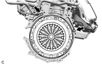
Check that the 2 knock pins are installed to the engine assembly before installing the manual transaxle assembly.
Align the input shaft with the clutch disc assembly and install the manual transaxle assembly to the engine assembly.
Install the 7 bolts.
- Torque:
- 33 N*m (337 kgf*cm, 24 ft.*lbf)
- NOTICE:
- ·
Make sure that the wire harness or similar items are not pinched between the contact surfaces.
·Do not forcibly pry on the manual transaxle assembly when installing it to the engine assembly.
·Do not apply excessive force to the manual transaxle assembly as this will break the input shaft.
·Make sure that the 2 knock pins fit securely into the holes when installing the manual transaxle assembly to the engine assembly.
·Make sure that the contact surfaces of the engine assembly and manual transaxle assembly are flat against each other before tightening the bolts.
13.CONNECT WIRE HARNESS
Connect the back-up light switch assembly connector and engage the clamp.
28100
14.INSTALL STARTER ASSEMBLY
11363A
15.INSTALL FLYWHEEL HOUSING SIDE COVER
12371A
16.TEMPORARILY INSTALL REAR ENGINE MOUNTING INSULATOR
12361A
17.TEMPORARILY INSTALL FRONT ENGINE MOUNTING INSULATOR
18.INSTALL ENGINE ASSEMBLY WITH TRANSAXLE