CLUTCH CLUTCH UNIT(for EC60) INSTALLATION
CAUTION / NOTICE / HINT
- NOTICE:
-
When the manual transaxle assembly is removed, be sure to use a new clutch release with bearing cylinder assembly and new installation bolts. Removal of the transaxle allows the compressed clutch release with bearing cylinder assembly to return to its original position. Dust from the moving section may damage the seal of the clutch release with bearing cylinder assembly, possibly causing clutch fluid leaks.
PROCEDURE

 31250
1.INSTALL CLUTCH DISC ASSEMBLY
31250
1.INSTALL CLUTCH DISC ASSEMBLY
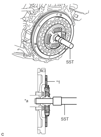
| *1 | Clutch Disc Assembly |
| *a | Flywheel Sub-assembly Side |
Insert SST into the clutch disc assembly, then insert them both into the flywheel sub-assembly.
- SST
- 09301-00210
- NOTICE:
-
Insert the clutch disc assembly in the correct direction.
31210
2.INSTALL CLUTCH COVER ASSEMBLY
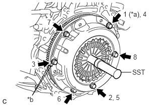
| *a | Temporarily Install |
| *b | Matchmark |
Align the matchmark on the clutch cover assembly with the one on the flywheel sub-assembly.
Following the procedure shown in the illustration, tighten the 6 bolts in order, starting with the bolt located near the knock pin at the top.
- SST
- 09301-00210
- Torque:
- 19.1 N*m (195 kgf*cm, 14 ft.*lbf)
- HINT:
- ·
Following the order in the illustration, tighten the bolts evenly one at a time.
·Move SST up and down, right and left lightly after checking that the clutch disc assembly is in the center, and tighten the bolts.
31210
3.INSPECT AND ADJUST CLUTCH COVER ASSEMBLY
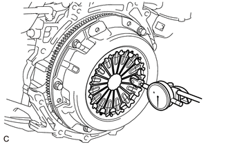
Using a dial indicator with a roller instrument, check the diaphragm spring tip alignment.
- Maximum Non-alignment:
0.5 mm (0.0197 in.)
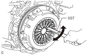
If the alignment is not as specified, using SST, adjust the diaphragm spring tip alignment.
- SST
- 09333-00013
31400
4.INSTALL CLUTCH RELEASE WITH BEARING CYLINDER ASSEMBLY
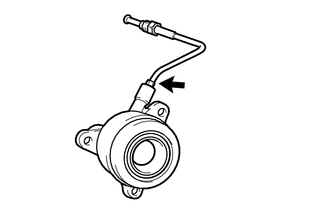
Temporarily install the bleeder clutch release tube to a new clutch release with bearing cylinder assembly.
Clean and degrease all installation surfaces for the clutch release with bearing cylinder assembly.
Install the clutch release with bearing cylinder assembly with 3 new bolts.
- Torque:
- 22.5 N*m (229 kgf*cm, 17 ft.*lbf)
- NOTICE:
- ·
The clutch release with bearing cylinder assembly and installation bolts cannot be reused and must be replaced with new ones.
·Clean and degrease all installation surfaces and make sure that the clutch release with bearing cylinder assembly fits securely with the manual transaxle assembly during installation. The first bolt should be tightened by hand while holding the clutch release with bearing cylinder assembly.
·Ensure that none of the clutch spline grease adheres to the clutch release with bearing cylinder assembly.
·The clutch release with bearing cylinder assembly cannot be disassembled.
Install the clutch tube boot to the manual transaxle assembly.
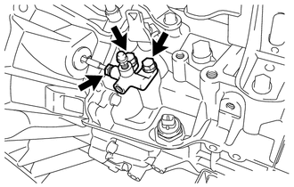
Temporarily install the bleeder clutch release tube to the clutch release bleeder sub-assembly.
Temporarily install the clutch release bleeder sub-assembly with the 2 bolts.
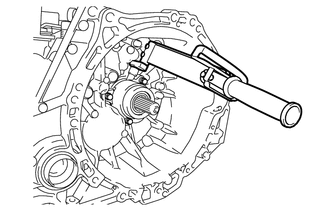
Using a 10 mm union nut wrench, install the bleeder clutch release tube to the clutch release with bearing cylinder assembly.
- Torque:
- 15.2 N*m (155 kgf*cm, 11 ft.*lbf)
- NOTICE:
- ·
Use a torque wrench with a fulcrum length of 250 mm (9.84 in.).
·Use the torque value compensation formula to calculate the torque value for use when a torque wrench is combined with a tool such as a union nut wrench.
Click hereGeneral>INTRODUCTION>REPAIR INSTRUCTION>PRECAUTION
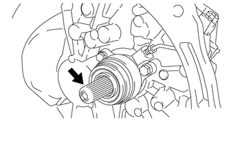

|
Clutch Spline Grease |
Apply clutch spline grease to the input shaft splines.
- Grease:
Toyota Genuine Clutch Spline Grease or equivalent
31407B
5.REMOVE CLUTCH RELEASE BLEEDER SUB-ASSEMBLY
Disconnect the bleeder clutch release tube from the clutch release bleeder sub-assembly.
Remove the 2 bolts and clutch release bleeder sub-assembly.
6.INSPECT CLUTCH PIPE LINE
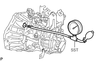
Using SST, apply pressure of 100 kPa (1.0 kgf/cm2, 15 psi) to the clutch pipe location shown in the illustration and confirm that pressure is maintained for 15 seconds or more.
- SST
- 09992-00242
If the pressure drops, replace the bleeder clutch release tube.
31407B
7.INSTALL CLUTCH RELEASE BLEEDER SUB-ASSEMBLY
Temporarily install the bleeder clutch release tube to the clutch release bleeder sub-assembly.
Install the 2 bolts and clutch release bleeder sub-assembly to the manual transaxle assembly.
- Torque:
- 16.7 N*m (170 kgf*cm, 12 ft.*lbf)
Using a 10 mm union nut wrench, connect the bleeder clutch release tube to the clutch release bleeder sub-assembly.
- Torque:
- 15.2 N*m (155 kgf*cm, 11 ft.*lbf)
- NOTICE:
- ·
Use a torque wrench with a fulcrum length of 250 mm (9.84 in.).
·Use the torque value compensation formula to calculate the torque value for use when a torque wrench is combined with a tool such as a union nut wrench.
Click hereGeneral>INTRODUCTION>REPAIR INSTRUCTION>PRECAUTION
31482
8.INSTALL CLUTCH RELEASE CYLINDER TO FLEXIBLE HOSE TUBE
Using a 10 mm union nut wrench, install the clutch release cylinder to flexible hose tube to the clutch release bleeder sub-assembly.
- Torque:
- 15.2 N*m (155 kgf*cm, 11 ft.*lbf)
- NOTICE:
- ·
Use a torque wrench with a fulcrum length of 250 mm (9.84 in.).
·Use the torque value compensation formula to calculate the torque value for use when a torque wrench is combined with a tool such as a union nut wrench.
Click hereGeneral>INTRODUCTION>REPAIR INSTRUCTION>PRECAUTION
Install the 2 clamps to the manual transaxle assembly with the 2 bolts.
- Torque:
- 8.0 N*m (82 kgf*cm, 71 in.*lbf)
30300
9.INSTALL MANUAL TRANSAXLE ASSEMBLY