LIGHTING (INT) LIGHTING SYSTEM Engine Switch Illumination Circuit
DESCRIPTION
The illuminated entry system controls the engine switch illumination.
WIRING DIAGRAM
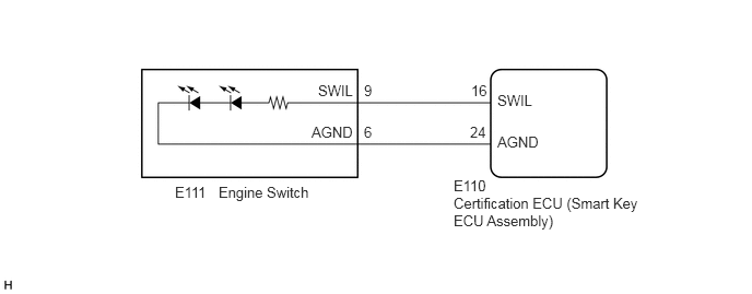
2.969,1.177 3.396,1.354
0.427,0.177
10
false
AGND
4.74,1.271 5.167,1.448
0.427,0.177
10
false
AGND
3.031,0.781 3.771,1.156
0.74,0.375
10
false
SWIL
4.74,0.875 5.51,1.198
0.771,0.323
10
false
SWIL
4.479,1.177 4.656,1.354
0.177,0.177
10
false
24
4.49,0.781 4.667,0.958
0.177,0.177
10
false
16
3.469,1.177 3.563,1.354
0.094,0.177
10
false
6
3.469,0.781 3.563,0.958
0.094,0.177
10
false
9
1.667,1.75 2.021,1.917
0.354,0.167
10
false
E111
2.083,1.75 3.781,2.104
1.698,0.354
10
false
Engine Switch
4.323,1.688 4.833,1.906
0.51,0.219
10
false
E110
4.323,1.854 6.135,2.188
1.813,0.333
10
false
Certification ECU (Smart Key ECU Assembly)
PROCEDURE
1.PERFORM ACTIVE TEST USING GTS
a.
Connect the GTS to the DLC3.
b.
Turn the ignition switch to ON.
c.
Turn the GTS on.
d.
Enter the following menus: Body Electrical / Entry&Start / Active Test.
e.
Perform the Active Test according to the display on the GTS.
- Body Electrical > Entry&Start > Active Test
-
Tester Display Measurement Item Control Range Diagnostic Note Power/Engine SW Light Engine switch illumination ON or OFF -
- Body Electrical > Entry&Start > Active Test
-
Tester Display Power/Engine SW Light - 50004 125 27
- OK:
Engine switch illumination comes on.
- Result:
Proceed to OK NG
OK
PROCEED TO NEXT SUSPECTED AREA SHOWN IN PROBLEM SYMPTOMS TABLE
NG
2.INSPECT ENGINE SWITCH
2.INSPECT ENGINE SWITCH
a.
Remove the engine switch.
Click hereEngine / Hybrid System>2ZR-FE STARTING>ENGINE SWITCH>REMOVAL
b.
Inspect the engine switch.
Click hereEngine / Hybrid System>2ZR-FE STARTING>ENGINE SWITCH>INSPECTION
- Result:
Proceed to OK NG
OK
3.CHECK HARNESS AND CONNECTOR (ENGINE SWITCH - CERTIFICATION ECU (SMART KEY ECU ASSEMBLY))
NG
3.CHECK HARNESS AND CONNECTOR (ENGINE SWITCH - CERTIFICATION ECU (SMART KEY ECU ASSEMBLY))
a.
Disconnect the E110 certification ECU (smart key ECU assembly) connector.
b.
Measure the resistance according to the value(s) in the table below.
- Standard Resistance:
Tester Connection Condition Specified Condition E111-9 (SWIL) - E110-16 (SWIL) Always Below 1 Ω E111-6 (AGND) - E110-24 (AGND) Always Below 1 Ω E111-9 (SWIL) or E110-16 (SWIL) - Body ground Always 10 kΩ or higher E111-6 (AGND) or E110-24 (AGND) - Body ground Always 10 kΩ or higher
- Result:
Proceed to OK NG
OK
REPLACE CERTIFICATION ECU (SMART KEY ECU ASSEMBLY)
NG
REPAIR OR REPLACE HARNESS OR CONNECTOR